Industrial automation has transformed modern manufacturing by improving productivity, reducing manual intervention, and ensuring consistent product quality. At the heart of every automated production line lies one essential technology—industrial sensors. Whether it is detecting the presence of a product on a conveyor, measuring the level of liquid in a storage tank, or monitoring the precise position of a robotic arm, sensors provide the real-time information needed for automation systems to make intelligent decisions.
Understanding the Types of Sensors Used in Industrial Automation is essential for automation engineers, maintenance teams, OEM machine builders, procurement professionals, and plant managers. Choosing the correct sensor not only improves machine performance but also reduces downtime, enhances workplace safety, and lowers maintenance costs.
Think of sensors as the eyes, ears, and nervous system of an industrial automation setup. Programmable Logic Controllers (PLCs), SCADA systems, robots, servo drives, and industrial computers depend on accurate sensor data to execute precise control actions. Without reliable sensors, even the most advanced automation system cannot perform efficiently.
From automotive assembly plants and pharmaceutical manufacturing facilities to food processing units and textile mills, industrial sensors are used to detect objects, measure distances, identify colors, monitor temperatures, inspect products, and ensure process accuracy.
In this comprehensive guide, we’ll explore the most widely used Industrial Automation Sensors, explain how they work, discuss their advantages and limitations, and share practical examples based on real industrial environments.
Why Are Sensors So Important in Industrial Automation?
Every automated process begins with data collection. Sensors convert physical conditions such as proximity, pressure, temperature, light, vibration, level, or movement into electrical signals that control systems can interpret.
Without sensors:
- Machines cannot detect products.
- Robots cannot determine position.
- Conveyors cannot stop at the correct location.
- Quality inspection becomes unreliable.
- Safety systems cannot detect human presence.
- Predictive maintenance becomes impossible.
Modern factories increasingly rely on Industrial Process Sensors to improve operational efficiency and support Industry 4.0 initiatives.
Key Benefits of Industrial Automation Sensors
- Improve production accuracy
- Reduce human error
- Increase production speed
- Enable predictive maintenance
- Enhance worker safety
- Reduce machine downtime
- Improve quality control
- Support real-time monitoring
- Lower operating costs
- Enable smart manufacturing
Overview of Different Industrial Sensor Types
| Sensor Type | Primary Function | Common Applications |
| Capacitive Sensor | Detects metallic and non-metallic objects | Packaging, plastics, food |
| Fiber Optic Sensor | Detects tiny objects in confined spaces | Semiconductor, pharmaceutical |
| Inductive Sensor | Detects metal objects | CNC, robotics, conveyors |
| Industrial Laser Sensor | Precision distance measurement | Robotics, automotive |
| Measurement Sensor | Measures dimensions and displacement | Quality inspection |
| Photoelectric Sensor | Object detection using light | Packaging, logistics |
| Ultrasonic Sensor | Distance measurement using sound | Tank level monitoring |
| Colour Mark Sensor | Detects printed marks and colors | Printing, packaging |
| Label Gap Sensor | Detects transparent labels | Bottle labeling |
| Vibration & Temperature Sensor | Equipment health monitoring | Predictive maintenance |
| Hydrostatic Level Sensor | Liquid level measurement | Water treatment, chemical plants |
1. Capacitive Sensors
What is a Capacitive Sensor?
A capacitive sensor is a non-contact Industrial Detection Sensor designed to detect both metallic and non-metallic materials by sensing changes in capacitance.
Unlike inductive sensors, which only detect metals, capacitive sensors can identify materials such as:
- Plastic
- Wood
- Glass
- Liquids
- Powders
- Granules
- Paper
- Ceramic
- Food products
This versatility makes them highly valuable across diverse industrial applications.
Working Principle
A capacitive sensor consists of two conductive plates that create an electric field. When an object enters this field, it changes the dielectric constant between the plates, altering the capacitance. The sensor’s internal electronics detect this change and generate an output signal.
How It Works
- The sensor continuously generates an electrostatic field.
- An object approaches the sensing face.
- The capacitance changes based on the object’s material.
- The internal oscillator detects the variation.
- The output switches ON or OFF.
- The PLC receives the signal and executes the programmed action.
Construction
A typical capacitive sensor includes:
- Sensing electrode
- Oscillator circuit
- Signal amplifier
- Trigger circuit
- Output transistor
- Protective housing (often IP67-rated)
Features
- Detects metallic and non-metallic objects
- Adjustable sensing distance
- Compact design
- Non-contact detection
- Long service life
- Resistant to wear
- Suitable for harsh industrial environments
Advantages
- Detects almost any material
- No mechanical contact required
- Reliable in dusty environments
- High repeatability
- Minimal maintenance
- Cost-effective solution
Limitations
- Short sensing range
- Sensitive to moisture buildup
- Temperature variations may affect performance
- Requires proper sensitivity adjustment
- Dust accumulation can cause false triggering if neglected
Industrial Applications
Capacitive sensors are widely used for:
- Bottle detection
- Plastic container counting
- Powder level monitoring
- Grain detection
- Packaging inspection
- Filling machines
- Pharmaceutical tablet detection
- Food packaging lines
- Hopper level sensing
Industries Using Capacitive Sensors
- Food processing
- Pharmaceutical
- Plastic manufacturing
- Packaging
- Agriculture
- Chemical plants
- Textile industry
Selection Tips
When selecting a capacitive sensor:
- Consider the material to be detected.
- Verify the required sensing distance.
- Choose an appropriate IP rating for the environment.
- Ensure compatibility with your PLC input voltage.
- Select adjustable sensitivity for varying product types.
Maintenance Tips
- Clean the sensing surface regularly.
- Avoid excessive moisture accumulation.
- Inspect cable connections.
- Periodically verify sensitivity settings.
- Replace damaged housings immediately.
Practical Example
In a flour packaging plant, capacitive sensors monitor the level of flour inside storage hoppers. When the level drops below a predefined point, the PLC automatically activates the feed conveyor to refill the hopper, ensuring uninterrupted production.
Common Mistakes to Avoid
- Mounting too close to metal structures
- Incorrect sensitivity adjustment
- Ignoring environmental moisture
- Choosing insufficient sensing distance
- Skipping routine cleaning
2. Fiber Optic Sensors
What is a Fiber Optic Sensor?
Fiber optic sensors use light transmitted through optical fibers to detect objects or measure changes in an environment. They are ideal for applications requiring high precision in confined spaces or harsh conditions.
The sensing head is extremely compact, while the amplifier can be mounted away from the sensing area, making these sensors suitable for installations with limited space.
Working Principle
A light source, typically an LED or laser, sends light through an optical fiber. When the light reflects from or is interrupted by a target, the receiving fiber carries the altered signal back to the amplifier, which processes it and produces an electrical output.
How It Works
- Light travels through the transmitting fiber.
- The target reflects or blocks the light.
- The receiving fiber captures the change.
- The amplifier analyzes the signal.
- The PLC receives the switching output.
Construction
Components include:
- Optical fiber cable
- LED or laser emitter
- Receiver
- Amplifier unit
- Signal processor
- Protective housing
Features
- Extremely small sensing head
- High-speed response
- Excellent precision
- Immune to electromagnetic interference
- Flexible installation
- Long sensing life
Advantages
- Suitable for tiny object detection
- High accuracy
- Operates in electrically noisy environments
- Resistant to high temperatures when fibers are appropriately selected
- Ideal for confined spaces
Limitations
- Higher initial cost
- Delicate fiber cables require careful handling
- Alignment is critical
- Requires periodic cleaning of optical surfaces
Industrial Applications
Fiber optic sensors are commonly used in:
- Electronic component assembly
- Pharmaceutical packaging
- Semiconductor manufacturing
- PCB inspection
- High-speed counting
- Precision assembly machines
Industries Using Fiber Optic Sensors
- Electronics
- Medical device manufacturing
- Pharmaceutical
- Semiconductor
- Robotics
- Packaging
Selection Tips
- Determine sensing distance.
- Choose through-beam or reflective type.
- Select appropriate fiber material.
- Consider ambient temperature.
- Ensure amplifier compatibility.
Maintenance Tips
- Keep fiber ends clean.
- Prevent cable bending beyond recommended limits.
- Check optical alignment.
- Inspect connectors regularly.
Practical Example
In a pharmaceutical blister packaging machine, fiber optic sensors detect individual tablets before sealing. If a cavity is empty, the PLC rejects the package, preventing defective products from reaching customers.
Common Mistakes to Avoid
- Excessive cable bending
- Dirty optical surfaces
- Incorrect amplifier settings
- Improper fiber alignment
- Ignoring environmental contamination
3. Inductive Sensors
What is an Inductive Sensor?
Inductive sensors are among the most widely used Factory Automation Sensors for detecting metallic objects without physical contact. They are highly reliable, durable, and capable of operating in demanding industrial environments.
These sensors generate an electromagnetic field that changes when a conductive metal object enters the sensing range.
Working Principle
An oscillator inside the sensor creates a high-frequency electromagnetic field. When a metal target enters this field, eddy currents are induced in the target, reducing the oscillator’s amplitude. Once this change reaches a threshold, the sensor switches its output.
How It Works
- The sensor emits an electromagnetic field.
- A metal object enters the sensing zone.
- Eddy currents form in the target.
- Oscillator energy decreases.
- The trigger circuit activates.
- The output changes state and sends a signal to the PLC.
Construction
Typical components include:
- Ferrite core
- Copper coil
- Oscillator
- Demodulator
- Trigger circuit
- Output stage
- Rugged metal or plastic housing
Features
- Non-contact metal detection
- High switching frequency
- Long operating life
- Shock-resistant
- Oil-resistant
- Dust-resistant
- Compact design
Advantages
- Extremely reliable
- Minimal maintenance
- High repeatability
- Fast response time
- Excellent durability
- Performs well in oily and dusty environments
Limitations
- Detects only metallic objects
- Limited sensing distance
- Detection range varies by metal type
- Stainless steel may have shorter sensing distances than mild steel
Industrial Applications
Inductive sensors are widely used for:
- Metal part detection
- CNC machine positioning
- Conveyor automation
- Robot positioning
- Machine tool monitoring
- Cylinder position sensing
- Gear tooth counting
- Limit detection
Industries Using Inductive Sensors
- Automotive manufacturing
- Steel plants
- Robotics
- Machine tools
- Packaging machinery
- Material handling
- CNC machining
- Metal fabrication
Selection Tips
- Match the sensing distance to the application.
- Consider flush or non-flush mounting.
- Verify voltage compatibility.
- Choose an IP67 or higher rating for harsh environments.
- Ensure suitable output type (PNP, NPN, NO, NC).
Maintenance Tips
- Inspect for physical damage.
- Remove metal chips from the sensing face.
- Check mounting tightness.
- Verify switching distance during preventive maintenance.
- Protect cables from mechanical stress.
Practical Example
In an automotive welding line, inductive sensors confirm that metal body panels are correctly positioned before robotic welding begins. If a panel is missing or misaligned, the PLC stops the welding sequence, preventing equipment damage and ensuring weld quality.
Common Mistakes to Avoid
- Attempting to detect non-metallic objects
- Mounting too close to adjacent metal surfaces without considering installation guidelines
- Ignoring the reduced sensing range for different metals
- Using sensors with inadequate environmental protection
- Neglecting periodic inspection in environments with heavy metal debris
4. Industrial Laser Sensors
What is an Industrial Laser Sensor?
Industrial Laser Sensors are high-precision Industrial Automation Sensors that use a focused laser beam to detect objects, measure distances, determine position, inspect dimensions, and perform quality control with exceptional accuracy.
Unlike conventional proximity sensors, laser sensors can measure tiny positional changes down to microns, making them ideal for precision manufacturing and automated inspection systems.
Today, Industrial Laser Sensors are widely used in Industry 4.0-enabled factories where high-speed production demands continuous and accurate monitoring.
Working Principle
Industrial laser sensors operate by transmitting a laser beam toward a target. The reflected light is analyzed using one of several measurement methods:
- Laser Triangulation
- Time of Flight (ToF)
- Phase Shift Measurement
- Confocal Measurement (for ultra-high precision)
The sensor calculates the distance or detects an object’s presence based on the reflected laser beam.
How It Works
- A semiconductor laser emits a focused beam.
- The beam strikes the target object.
- The reflected beam returns to the receiver.
- Internal electronics analyze the reflection.
- Distance or position is calculated.
- Data is transmitted to the PLC or industrial controller.
Many modern sensors also provide analog outputs and industrial Ethernet communication for real-time monitoring.
Construction
Typical components include:
- Laser diode
- Optical lens
- Receiver (CMOS/CCD detector)
- Signal processor
- Microcontroller
- Output circuit
- Protective industrial housing
Features
- Extremely high accuracy
- Long sensing distance
- Fast response time
- Non-contact measurement
- Micron-level precision
- Digital and analog outputs
- Suitable for dynamic measurements
Advantages
- Very accurate measurements
- Detects small objects
- Long operational life
- High-speed detection
- No mechanical wear
- Suitable for automated inspection
- Works well in robotic applications
Limitations
- Performance may decrease on highly reflective or transparent surfaces
- Dust or smoke can affect measurement accuracy
- Higher investment compared to basic proximity sensors
- Requires proper alignment during installation
Industrial Applications
Industrial laser sensors are commonly used for:
- Robot positioning
- Weld seam inspection
- Automotive body alignment
- Thickness measurement
- PCB inspection
- Dimension measurement
- Packaging inspection
- Material edge detection
- Surface profile inspection
Industries Using Industrial Laser Sensors
- Automotive
- Aerospace
- Electronics
- Steel manufacturing
- Packaging
- Robotics
- Semiconductor
- CNC machining
Selection Tips
Consider the following before selecting a laser sensor:
- Required measuring range
- Target surface characteristics
- Required accuracy
- Ambient lighting
- Environmental contamination
- Response speed
- Communication interface
- IP protection rating
Maintenance Tips
- Clean optical lenses regularly.
- Avoid scratches on the lens.
- Verify alignment periodically.
- Inspect mounting brackets for vibration.
- Check cable integrity.
Practical Real-World Example
In an automotive assembly plant, laser displacement sensors continuously measure the gap between car doors and the vehicle body. If the gap exceeds the specified tolerance, the PLC automatically diverts the vehicle for rework, ensuring consistent build quality.
Common Mistakes to Avoid
- Ignoring reflective surface effects
- Mounting the sensor on unstable structures
- Failing to clean optical components
- Selecting insufficient measurement range
- Overlooking ambient light interference
5. Measurement Sensors
What are Measurement Sensors?
Measurement Sensors are specialized industrial sensors designed to measure physical parameters such as:
- Distance
- Thickness
- Diameter
- Width
- Height
- Position
- Runout
- Flatness
- Displacement
These sensors play a vital role in quality assurance and process control by providing accurate, repeatable measurements.
Working Principle
Depending on the application, measurement sensors use different technologies such as:
- Laser triangulation
- Eddy current sensing
- Capacitive measurement
- Optical imaging
- Ultrasonic measurement
- Contact probes (LVDTs)
The sensor converts the measured physical value into an electrical signal that can be processed by the control system.
How It Works
- The sensor scans the target.
- Internal electronics calculate the measurement.
- The value is digitized.
- Measurement data is sent to the PLC, SCADA, or industrial PC.
- The control system compares it with predefined tolerances.
Features
- High precision
- Real-time monitoring
- Continuous measurement
- Multiple output options
- Compact design
- High repeatability
Advantages
- Improves product quality
- Reduces scrap
- Enables automatic inspection
- Supports statistical process control (SPC)
- Eliminates manual measurement errors
Limitations
- Higher cost
- Requires calibration
- Sensitive to installation accuracy
- Performance depends on application conditions
Industrial Applications
Measurement sensors are used for:
- Sheet thickness measurement
- Pipe diameter inspection
- Bearing inspection
- Roll positioning
- CNC dimensional verification
- Packaging quality control
- Assembly verification
Industries Using Measurement Sensors
- Automotive
- Steel
- Pharmaceutical
- Plastic manufacturing
- Electronics
- Packaging
- Aerospace
Selection Tips
- Required measurement accuracy
- Environmental conditions
- Surface finish
- Measuring speed
- Output compatibility
- Mounting requirements
Maintenance Tips
- Perform periodic calibration.
- Keep measuring surfaces clean.
- Protect from excessive vibration.
- Verify measurement accuracy using certified standards.
Practical Example
In a steel rolling mill, laser measurement sensors continuously monitor sheet thickness. If the thickness deviates from the target value, the rolling mill automatically adjusts the roller gap, minimizing material waste and maintaining product quality.
Common Mistakes to Avoid
- Skipping calibration schedules
- Installing on unstable mounting surfaces
- Ignoring thermal expansion effects
- Using sensors beyond their specified range
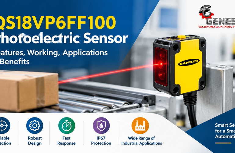
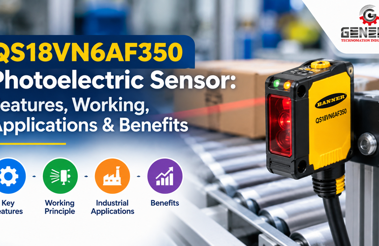
6. Photoelectric Sensors
What is a Photoelectric Sensor?
Photoelectric Sensors are among the most widely used Factory Automation Sensors for detecting objects without physical contact. They use a beam of light to identify the presence, absence, or movement of an object.
Unlike inductive sensors, photoelectric sensors can detect both metallic and non-metallic materials over longer distances.
Working Principle
A photoelectric sensor emits a beam of infrared or visible light. When an object interrupts or reflects the beam, the receiver detects the change and switches the output.
The three main types are:
- Through-beam
- Retro-reflective
- Diffuse reflective
How It Works
- The transmitter emits light.
- The beam travels toward the receiver or reflector.
- An object interrupts or reflects the beam.
- The receiver detects the change.
- The PLC receives the switching signal.
Features
- Long sensing distance
- High-speed detection
- Non-contact operation
- Detects almost any material
- Compact design
Advantages
- Long detection range
- Reliable operation
- High switching speed
- Suitable for transparent and opaque objects (with appropriate models)
- Easy installation
Limitations
- Dust accumulation on lenses may reduce performance.
- Bright ambient light may affect certain models.
- Proper alignment is essential.
- Reflective surfaces may require specialized sensor settings.
Industrial Applications
- Conveyor object detection
- Carton counting
- Bottle detection
- Warehouse automation
- AGV navigation
- Packaging inspection
- Robot part detection
Industries Using Photoelectric Sensors
- Packaging
- Food processing
- Logistics
- Warehousing
- Pharmaceutical
- Automotive
- Consumer goods manufacturing
Selection Tips
- Choose the appropriate sensing mode.
- Verify detection distance.
- Consider object color and surface.
- Select suitable housing and IP rating.
- Ensure compatibility with the control system.
Maintenance Tips
- Clean optical lenses regularly.
- Check alignment after maintenance activities.
- Inspect cables for damage.
- Test switching performance during preventive maintenance.
Practical Real-World Example
In a beverage bottling line, photoelectric sensors detect incoming bottles before the filling station. If no bottle is present, the filling valve remains closed, preventing product spillage and reducing waste.
Common Mistakes to Avoid
- Misalignment of transmitter and receiver
- Dirty lenses
- Incorrect sensing mode selection
- Ignoring ambient lighting conditions
7. Ultrasonic Sensors
What is an Ultrasonic Sensor?
Ultrasonic Sensors detect objects and measure distances using high-frequency sound waves instead of light. Because they are unaffected by color, transparency, or surface finish, they are ideal for challenging detection applications.
Working Principle
The sensor emits ultrasonic pulses. These sound waves travel through the air, strike the target, and return as echoes. The sensor measures the time taken for the echo to return and calculates the distance.
How It Works
- The sensor emits an ultrasonic pulse.
- The sound wave travels toward the target.
- The target reflects the sound.
- The sensor receives the echo.
- Distance is calculated using the time-of-flight principle.
- Output is sent to the controller.
Features
- Detects transparent objects
- Measures liquid levels
- Long sensing range
- Works in dusty environments
- Non-contact measurement
Advantages
- Independent of object color
- Reliable for transparent materials
- Excellent for liquid level measurement
- Performs well in dusty environments
- Low maintenance
Limitations
- Temperature variations can slightly affect measurement accuracy.
- Soft materials may absorb sound.
- Foam can interfere with liquid level detection.
- Wind and strong air currents may influence readings in some installations.
Industrial Applications
- Tank level monitoring
- Roll diameter measurement
- Vehicle detection
- Conveyor positioning
- Bulk material monitoring
- Packaging systems
Industries Using Ultrasonic Sensors
- Chemical processing
- Water treatment
- Food processing
- Packaging
- Cement plants
- Agriculture
- Logistics
Selection Tips
- Required sensing distance
- Tank geometry
- Material characteristics
- Temperature range
- IP rating
Maintenance Tips
- Keep the transducer face clean.
- Inspect for condensation.
- Verify calibration periodically.
- Check mounting orientation.
Practical Example
A wastewater treatment facility uses ultrasonic sensors to monitor the level of water in storage tanks. When the level reaches a predefined limit, pumps start or stop automatically, preventing overflow and ensuring efficient operation.
Common Mistakes to Avoid
- Mounting too close to tank walls
- Ignoring blind zones
- Incorrect sensor angle
- Neglecting environmental factors
8. Colour Mark Sensors
What is a Colour Mark Sensor?
A Colour Mark Sensor, also known as a contrast sensor or print mark sensor, is a specialized industrial sensor designed to detect printed color marks, registration marks, contrast differences, and labels on moving materials. These sensors play a critical role in high-speed packaging, printing, converting, and labeling machines where precise positioning is essential.
Unlike standard photoelectric sensors that primarily detect object presence, colour mark sensors differentiate between colors and contrast levels with exceptional speed and accuracy. They help synchronize machine operations by ensuring that cutting, sealing, labeling, or printing occurs at the correct position.
Working Principle
Colour mark sensors use RGB (Red, Green, and Blue) LEDs or white light LEDs to illuminate the target surface. The reflected light is analyzed by an internal photodetector, which compares the intensity and wavelength of the reflected light.
When the sensor detects the programmed color or contrast difference, it sends an output signal to the PLC or machine controller, triggering the next operation.
How It Works
- The sensor emits colored or white light.
- The moving material reflects the light.
- The receiver measures the reflected intensity.
- The processor compares the reading with the stored reference.
- Once the desired mark is detected, the sensor switches its output.
- The PLC executes the programmed machine function.
Construction
A typical colour mark sensor consists of:
- RGB LED light source
- Optical lens
- Photodiode receiver
- Digital signal processor
- Learning button or teach-in function
- Industrial housing with IP protection
- Output circuitry
Features
- High-speed detection
- Excellent color discrimination
- Automatic teach mode
- Compact design
- Stable performance on fast-moving materials
- Adjustable sensitivity
- LED status indicators
- Digital or analog outputs
Advantages
- Highly accurate registration mark detection
- Works at very high production speeds
- Reduces material wastage
- Improves cutting accuracy
- Easy setup with teach function
- Long service life
- Low maintenance requirements
Limitations
- Performance may decrease if the print quality is poor.
- Dust or ink buildup on the lens can affect accuracy.
- Extremely glossy materials may require sensor adjustment.
- Ambient lighting should be considered during installation.
Industrial Applications
Colour mark sensors are widely used in:
- Flexible packaging machines
- Printing presses
- Labeling systems
- Film cutting machines
- Carton manufacturing
- Textile printing
- Pharmaceutical blister packaging
- Food packaging equipment
Industries Using Colour Mark Sensors
- Packaging
- Printing
- Pharmaceutical
- Food processing
- Textile
- Consumer goods manufacturing
- Label production
Selection Tips
When selecting a colour mark sensor, consider:
- Type of material being inspected
- Color combinations
- Machine speed
- Sensing distance
- Required response time
- Mounting space
- Environmental conditions
Maintenance Tips
- Clean the optical lens regularly.
- Check sensor alignment after maintenance.
- Verify teach settings periodically.
- Remove ink or dust buildup.
- Inspect cables and connectors.
Practical Real-World Example
A snack packaging machine prints registration marks on plastic film. As the film moves through the machine at high speed, the colour mark sensor detects each registration mark and signals the PLC to activate the cutter. This ensures every package is cut precisely at the correct location, preventing product loss and maintaining a professional appearance.
Common Mistakes to Avoid
- Incorrect teach settings
- Dirty sensor lenses
- Mounting too far from the target
- Ignoring changes in packaging material
- Using a standard photoelectric sensor where color detection is required
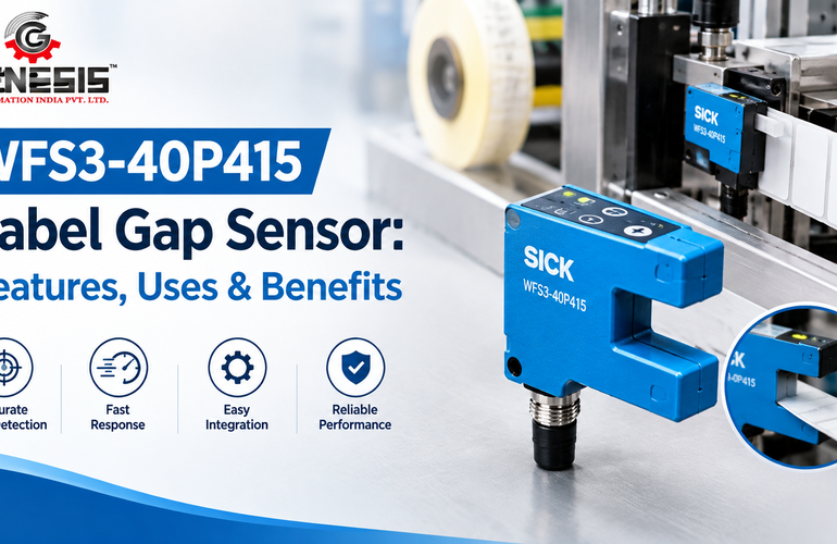
9. Label Gap Sensor / Fork Sensor
What is a Label Gap Sensor?
A Label Gap Sensor, commonly known as a Fork Sensor, is a precision sensor designed to detect the gap between labels on a backing paper. It is widely used in automatic labeling machines to ensure accurate label placement.
Fork sensors are especially effective for detecting transparent labels, thin films, and small gaps that conventional photoelectric sensors may struggle to identify.
Working Principle
The sensor uses infrared or visible light transmitted across a U-shaped fork. As the label web passes through the fork, the sensor detects the difference between the label and the gap, allowing precise positioning.
How It Works
- The label web passes through the sensor fork.
- Light continuously passes across the opening.
- Labels block or alter the light differently than the gaps.
- The sensor identifies each gap.
- The PLC receives the signal.
- The label dispenser stops exactly at the next dispensing position.
Construction
Main components include:
- U-shaped housing
- Light transmitter
- Receiver
- Digital processor
- Teach button
- Output electronics
Features
- High positioning accuracy
- Fast response time
- Compact construction
- Suitable for transparent labels
- Easy installation
- Automatic learning function
Advantages
- Accurate label positioning
- Supports high-speed labeling
- Reliable operation
- Minimal maintenance
- Detects small label gaps
- Excellent repeatability
Limitations
- Incorrect alignment affects performance.
- Label contamination can interfere with detection.
- Some specialty label materials may require sensor adjustment.
Industrial Applications
- Bottle labeling
- Carton labeling
- Barcode labeling
- Pharmaceutical packaging
- Cosmetic packaging
- Food labeling
- Logistics labeling
Industries Using Fork Sensors
- Pharmaceutical
- Food & Beverage
- Cosmetics
- Packaging
- Logistics
- Consumer products
Selection Tips
Choose based on:
- Label size
- Gap width
- Label transparency
- Machine speed
- Required accuracy
- Mounting configuration
Maintenance Tips
- Clean the sensor slot regularly.
- Remove adhesive residue.
- Verify label alignment.
- Check mounting tightness.
Practical Real-World Example
A pharmaceutical company uses fork sensors on a bottle labeling machine. Every bottle receives a label in exactly the same position, ensuring compliance with regulatory requirements and preventing rejected products due to misaligned labels.
Common Mistakes to Avoid
- Dirty sensor slot
- Incorrect sensitivity settings
- Poor label alignment
- Ignoring worn dispensing rollers
- Using unsuitable sensors for transparent labels
10. Vibration and Temperature Sensors
What are Vibration and Temperature Sensors?
Vibration and Temperature Sensors are essential Industrial Monitoring Sensors used to continuously monitor the health of rotating machinery and critical industrial equipment.
Rather than detecting products, these sensors monitor machine condition and are a key component of predictive maintenance programs.
By identifying abnormal vibration patterns or excessive temperatures early, maintenance teams can address issues before they lead to costly breakdowns.
Working Principle
Vibration Sensors
Most industrial vibration sensors use piezoelectric elements or MEMS (Micro-Electro-Mechanical Systems). Mechanical vibration generates electrical signals proportional to vibration amplitude and frequency.
Temperature Sensors
Temperature sensors commonly use:
- RTDs (Resistance Temperature Detectors)
- Thermocouples
- Thermistors
- Infrared sensors
These devices convert temperature changes into electrical signals for monitoring and control.
How They Work
- The sensor is mounted on critical equipment.
- It continuously measures vibration or temperature.
- Data is transmitted to the PLC, SCADA, or monitoring software.
- Alarm limits are compared against preset values.
- Maintenance personnel receive alerts if abnormal conditions are detected.
Construction
Typical components include:
- Sensing element
- Protective housing
- Signal conditioning electronics
- Connector or cable
- Mounting base
Features
- Continuous condition monitoring
- High reliability
- Supports predictive maintenance
- Real-time monitoring
- Easy integration with automation systems
- Digital communication support
Advantages
- Prevents unexpected failures
- Extends equipment life
- Reduces maintenance costs
- Improves production reliability
- Supports Industry 4.0 initiatives
- Enables remote monitoring
Limitations
- Requires proper sensor placement
- Alarm thresholds must be configured correctly
- Periodic calibration may be necessary
- Data interpretation requires technical knowledge
Industrial Applications
These sensors monitor:
- Electric motors
- Gearboxes
- Pumps
- Compressors
- Cooling towers
- Fans
- Turbines
- Conveyor drives
- CNC machine spindles
Industries Using Vibration and Temperature Sensors
- Automotive
- Power generation
- Cement
- Steel
- Chemical processing
- Mining
- Food processing
- Oil & Gas
- Paper manufacturing
Selection Tips
Consider:
- Measurement range
- Frequency response
- Mounting method
- Operating temperature
- Communication protocol
- Environmental protection
Maintenance Tips
- Inspect mounting bolts.
- Verify sensor calibration.
- Check cable integrity.
- Compare historical trends.
- Replace damaged sensors promptly.
Practical Real-World Example
In a cement manufacturing plant, vibration sensors installed on large conveyor drive motors detected a gradual increase in vibration levels caused by bearing wear. Maintenance engineers replaced the bearing during a planned shutdown, avoiding an unexpected production stoppage and costly emergency repairs.
Common Mistakes to Avoid
- Mounting sensors on loose surfaces
- Ignoring gradual trend changes
- Incorrect alarm settings
- Skipping periodic calibration
- Replacing sensors without identifying the root cause
11. Hydrostatic Level Sensors
What is a Hydrostatic Level Sensor?
A Hydrostatic Level Sensor is an Industrial Process Sensor used to measure the level of liquids in tanks, reservoirs, wells, and process vessels by measuring the pressure exerted by the liquid column above the sensor.
Because liquid pressure increases proportionally with depth, hydrostatic sensors provide a simple, reliable, and highly accurate method for continuous level measurement.
Working Principle
Hydrostatic level sensors operate according to the principle:
Pressure = Density × Gravity × Height
As the liquid level rises, the hydrostatic pressure at the sensor increases. An internal pressure-sensing element converts this pressure into an electrical signal proportional to the liquid level.
How It Works
- The sensor is submerged in the liquid.
- The liquid exerts pressure on the sensing diaphragm.
- The pressure element converts this force into an electrical signal.
- Signal conditioning electronics process the measurement.
- The PLC or SCADA system displays the liquid level and controls pumps or valves accordingly.
Construction
Typical components include:
- Stainless steel sensing diaphragm
- Pressure sensing element
- Signal conditioning electronics
- Vented cable (for atmospheric compensation)
- Protective housing
- Cable connection
Features
- Continuous level measurement
- High accuracy
- Excellent long-term stability
- Suitable for deep tanks and wells
- Corrosion-resistant construction
- Analog and digital outputs available
Advantages
- Reliable operation in demanding environments
- Minimal moving parts
- Low maintenance
- Suitable for large storage tanks
- Accurate measurement over wide depth ranges
- Easy integration with PLC and SCADA systems
Limitations
- Liquid density variations can affect accuracy.
- Not suitable for highly viscous materials without proper selection.
- Sensor diaphragms should be protected from abrasive slurries.
- Vent tubes must remain free from moisture blockage.
Industrial Applications
Hydrostatic level sensors are commonly used for:
- Water storage tanks
- Wastewater treatment plants
- Chemical storage tanks
- Fuel tanks
- Process vessels
- Bore wells
- Irrigation systems
- Cooling water reservoirs
Industries Using Hydrostatic Level Sensors
- Water treatment
- Chemical processing
- Food & Beverage
- Pharmaceutical
- Power plants
- Oil & Gas
- Agriculture
- Municipal infrastructure
Selection Tips
Before selecting a hydrostatic level sensor, evaluate:
- Liquid type and density
- Measuring range
- Required accuracy
- Process temperature
- Chemical compatibility of wetted materials
- Cable length
- Output signal (4–20 mA, 0–10 V, Modbus, etc.)
- Required IP rating and environmental protection
Maintenance Tips
- Inspect the sensing diaphragm for buildup or damage.
- Ensure the vent tube remains dry and unobstructed.
- Verify calibration during scheduled maintenance.
- Check cable insulation and strain relief.
- Compare readings against manual level measurements periodically.
Practical Real-World Example
A municipal water treatment facility uses hydrostatic level sensors in underground clear-water reservoirs. The sensors continuously monitor water levels and transmit data to the SCADA system. When the level drops below a predefined threshold, pumps start automatically, maintaining a consistent water supply while preventing dry-running conditions.
Common Mistakes to Avoid
- Selecting incompatible diaphragm materials for corrosive liquids
- Ignoring changes in liquid density during process design
- Installing the sensor at an incorrect depth
- Allowing moisture to enter the vent tube
- Neglecting periodic calibration and inspection
How to Choose the Right Industrial Sensor
Selecting the appropriate sensor is one of the most important decisions in any automation project. An incorrectly selected sensor can result in unreliable machine performance, frequent downtime, poor product quality, and increased maintenance costs.
1. Evaluate Environmental Conditions
Consider the operating environment before making a selection:
- Dust and powder
- Oil and grease
- Water exposure
- Humidity
- Chemical vapors
- Mechanical vibration
- Washdown requirements
Choose a sensor with an appropriate IP rating (such as IP67, IP68, or IP69K) and housing material suited to the application.
2. Determine the Detection Distance
Different sensor technologies have varying sensing ranges. For example:
- Inductive sensors are ideal for short-range metal detection.
- Photoelectric and laser sensors support longer detection distances.
- Ultrasonic sensors are effective for medium- to long-range distance and level measurement.
Always include a safety margin when specifying sensing distance.
3. Verify Material Compatibility
Match the sensing technology to the target material:
| Material | Recommended Sensor |
| Metal components | Inductive Sensor |
| Plastic or glass | Capacitive or Photoelectric Sensor |
| Transparent bottles | Ultrasonic or specialized Photoelectric Sensor |
| Printed registration marks | Colour Mark Sensor |
| Liquid levels | Hydrostatic or Ultrasonic Sensor |
| Precision dimensional checks | Laser or Measurement Sensor |
4. Check Accuracy and Response Time
High-speed packaging machines, robotics, and CNC systems often require millisecond response times and high repeatability. Ensure the sensor specifications meet the process requirements.
5. Consider Mounting Space
Evaluate available installation space and choose between cylindrical, rectangular, fork-type, or remote-head sensor designs as appropriate.
6. Confirm Communication Compatibility
Modern automation systems increasingly use digital communication. Verify compatibility with your PLC or control architecture, including:
- PNP or NPN switching outputs
- Analog outputs (4–20 mA, 0–10 V)
- IO-Link
- Modbus
- EtherNet/IP
- PROFINET
- EtherCAT (where applicable)
7. Assess Total Cost of Ownership
The lowest purchase price is not always the most economical option. Consider:
- Service life
- Maintenance requirements
- Spare part availability
- Technical support
- Calibration needs
- Downtime costs associated with sensor failure
Working with an experienced automation supplier can simplify sensor selection and ensure long-term reliability. Genesis Technomation India Private Limited offers a wide range of industrial automation sensors, application guidance, and technical consultation to help manufacturers, OEMs, and system integrators choose solutions that align with their production requirements.
Common Industrial Sensor Applications
Industrial sensors are fundamental components of modern automation systems. They enable machines to detect, measure, monitor, and respond to changing process conditions in real time. From high-speed packaging lines to complex process plants, sensors improve productivity, product quality, and operational safety.
Below are some of the most common Industrial Sensor Applications across manufacturing industries.
1. Packaging Industry
Packaging lines rely on multiple sensor technologies to maintain speed and accuracy.
Common Sensors Used
- Photoelectric Sensors
- Colour Mark Sensors
- Label Gap/Fork Sensors
- Capacitive Sensors
- Laser Sensors
Typical Applications
- Bottle detection
- Carton counting
- Film registration
- Label positioning
- Package inspection
- Conveyor synchronization
- Missing product detection
Practical Example:
A food packaging machine uses a colour mark sensor to detect registration marks on printed film while a fork sensor ensures labels are applied accurately to every package.
2. Pharmaceutical Industry
Pharmaceutical manufacturing demands extremely high accuracy and regulatory compliance.
Common Sensors
- Fiber Optic Sensors
- Laser Sensors
- Photoelectric Sensors
- Label Sensors
- Temperature Sensors
Applications
- Tablet counting
- Blister pack inspection
- Bottle filling verification
- Label inspection
- Batch tracking
- Sterile process monitoring
3. Food Processing Industry
Food manufacturing requires hygienic sensor designs capable of withstanding washdown environments.
Common Sensors
- Capacitive Sensors
- Ultrasonic Sensors
- Temperature Sensors
- Photoelectric Sensors
Applications
- Ingredient level monitoring
- Bottle detection
- Package counting
- Conveyor automation
- Cooking temperature monitoring
- Fill-level verification
4. Textile Industry
Automation improves production consistency in textile manufacturing.
Sensors Used
- Colour Mark Sensors
- Fiber Optic Sensors
- Photoelectric Sensors
Applications
- Fabric alignment
- Color registration
- Roll diameter measurement
- Yarn break detection
- Position monitoring
5. Automotive Manufacturing
Automotive plants contain thousands of industrial sensors controlling robots and assembly systems.
Common Sensors
- Inductive Sensors
- Laser Sensors
- Measurement Sensors
- Vibration Sensors
- Temperature Sensors
Applications
- Robot positioning
- Weld verification
- Body alignment
- Component presence detection
- Conveyor automation
- Predictive maintenance
6. Steel Industry
Heavy industrial environments require rugged sensor solutions.
Applications
- Hot steel positioning
- Thickness measurement
- Roll monitoring
- Crane automation
- Billet detection
- Furnace temperature monitoring
7. Chemical Industry
Chemical plants depend on continuous process monitoring.
Sensors Used
- Hydrostatic Level Sensors
- Ultrasonic Sensors
- Temperature Sensors
Applications
- Tank level measurement
- Reactor monitoring
- Pump protection
- Chemical dosing
- Process control
8. Warehousing and Logistics
Modern warehouses increasingly rely on automation.
Applications
- Barcode positioning
- Conveyor tracking
- Pallet detection
- AGV navigation
- Automated storage systems
9. Conveyor Systems
Conveyors are found in almost every manufacturing facility.
Sensors Used
- Photoelectric Sensors
- Inductive Sensors
- Laser Sensors
Applications
- Product counting
- Jam detection
- Position sensing
- Sorting systems
- Transfer control
10. Robotics
Industrial robots require continuous sensor feedback.
Applications
- Position control
- Collision detection
- Part verification
- Tool positioning
- Assembly inspection
11. CNC Machines
Precision machining depends on reliable sensor inputs.
Applications
- Tool position monitoring
- Workpiece detection
- Axis positioning
- Temperature monitoring
- Tool wear detection
12. Process Automation
Process industries use sensors to maintain stable production conditions.
Applications
- Flow monitoring
- Pressure control
- Level measurement
- Temperature control
- Quality assurance
13. Water and Wastewater Treatment
Common Applications
- Tank level monitoring
- Pump automation
- Overflow prevention
- Flow measurement
- Water quality monitoring
Hydrostatic level sensors and ultrasonic sensors are widely used because of their reliability in harsh environments.
14. Material Handling Systems
Automation improves efficiency in warehouses and manufacturing plants.
Applications
- Forklift positioning
- Automated storage
- Pallet detection
- Crane positioning
- Material transfer
Benefits of Using Industrial Sensors
Selecting the appropriate Industrial Automation Sensors provides measurable benefits across manufacturing operations.
Improved Productivity
Real-time detection allows machines to operate continuously with minimal manual intervention, increasing throughput and reducing production bottlenecks.
Better Product Quality
Sensors verify dimensions, position, color, labels, and assembly accuracy, reducing defects and improving consistency.
Reduced Downtime
Condition-monitoring sensors identify potential equipment issues before they lead to failures, allowing maintenance to be scheduled during planned shutdowns.
Predictive Maintenance
Vibration and temperature sensors continuously monitor machine health, enabling maintenance teams to replace worn components before catastrophic failures occur.
Enhanced Worker Safety
Industrial safety sensors help protect personnel by detecting unsafe conditions, monitoring hazardous areas, and supporting machine safety functions in accordance with applicable standards.
Lower Operating Costs
Reliable sensors reduce:
- Product waste
- Machine failures
- Manual inspections
- Maintenance costs
- Production interruptions
Improved Energy Efficiency
Sensors help optimize equipment operation by ensuring machines run only when necessary and by monitoring process variables that affect energy consumption.
Industry 4.0 Readiness
Modern Smart Sensors equipped with digital communication protocols provide valuable data for analytics, remote monitoring, and connected manufacturing systems.
Common Problems with Industrial Sensors
Even the most reliable sensors require correct selection, installation, and maintenance. The following issues are commonly encountered in industrial environments.
1. Dust Contamination
Dust accumulation on sensing surfaces, particularly on photoelectric, laser, and colour mark sensors, can reduce detection reliability.
Solution
- Clean sensor lenses regularly.
- Install protective covers where appropriate.
- Include sensors in preventive maintenance schedules.
2. Moisture and Water Exposure
Water ingress may cause corrosion or false triggering if the sensor is not adequately protected.
Solution
- Select an appropriate IP-rated sensor.
- Use suitable cable glands and connectors.
- Inspect seals during maintenance.
3. Electrical Noise
Variable Frequency Drives (VFDs), welding equipment, and large motors can introduce electrical interference.
Solution
- Separate sensor cables from power cables.
- Use shielded cables where recommended.
- Ensure proper grounding practices.
4. Incorrect Sensor Selection
Using the wrong sensing technology often results in poor machine performance.
Examples
- Using an inductive sensor to detect plastic.
- Selecting a photoelectric sensor where an ultrasonic sensor is more suitable.
- Choosing an insufficient sensing range.
Solution
Evaluate:
- Target material
- Environmental conditions
- Detection distance
- Response time
- Accuracy requirements
5. Improper Installation
Incorrect mounting can reduce sensing performance and reliability.
Common Installation Errors
- Sensor misalignment
- Loose mounting brackets
- Incorrect sensing distance
- Improper cable routing
Solution
Always follow the manufacturer’s installation guidelines and verify sensor operation after installation.
6. Calibration Issues
Measurement sensors, hydrostatic level sensors, and condition-monitoring devices require periodic calibration to maintain accuracy.
Solution
- Follow recommended calibration intervals.
- Maintain calibration records.
- Use certified reference standards where applicable.
7. Poor Preventive Maintenance
Neglecting routine inspections increases the likelihood of unexpected failures.
Recommended Maintenance Checklist
- Clean sensing surfaces.
- Inspect cables and connectors.
- Check mounting hardware.
- Verify switching operation.
- Confirm calibration where applicable.
- Review historical performance trends.
Industrial Sensor Troubleshooting Guide
| Problem | Possible Cause | Recommended Solution |
| False triggering | Incorrect sensitivity or electrical noise | Adjust sensitivity, improve cable routing, and verify grounding |
| Sensor does not detect target | Wrong sensor type, excessive distance, or misalignment | Confirm sensor selection, reposition the sensor, and check the sensing range |
| Intermittent operation | Loose connections or mechanical vibration | Tighten connections, secure mounting, and inspect cables |
| Inaccurate measurements | Calibration drift or contamination | Clean the sensor and perform calibration according to the manufacturer’s recommendations |
| Frequent sensor failure | Harsh environment or incorrect IP rating | Choose a sensor with suitable environmental protection and housing materials |
| Communication errors | Network configuration or damaged cables | Verify communication settings, inspect connectors, and replace damaged cables if necessary |
Future Trends in Industrial Sensors
Industrial automation continues to evolve rapidly. Sensors are becoming smarter, more connected, and increasingly integrated with digital manufacturing systems.
Smart Sensors
Smart sensors incorporate onboard microprocessors capable of:
- Self-diagnostics
- Automatic configuration
- Digital communication
- Continuous health monitoring
These capabilities reduce maintenance time and simplify system integration.
Industrial Internet of Things (IIoT)
IIoT connects sensors directly to cloud platforms, manufacturing execution systems (MES), and enterprise software, enabling:
- Remote monitoring
- Real-time dashboards
- Performance analytics
- Centralized asset management
AI-Powered Monitoring
Artificial Intelligence analyzes sensor data to detect subtle patterns that may indicate developing equipment problems.
Typical applications include:
- Bearing failure prediction
- Motor health assessment
- Process optimization
- Energy management
- Automated quality inspection
Wireless Sensors
Wireless technologies reduce installation costs and simplify monitoring of equipment in difficult-to-access locations.
Benefits include:
- Reduced cabling
- Faster installation
- Flexible deployment
- Easy expansion
Predictive Maintenance
Predictive maintenance combines vibration, temperature, current, and other sensor data to forecast equipment failures before they occur.
This approach helps manufacturers:
- Reduce unexpected downtime
- Extend equipment life
- Improve maintenance planning
- Lower operating costs
Digital Twin Technology
A Digital Twin is a virtual representation of a physical asset or production process.
Sensor data continuously updates the digital model, enabling engineers to:
- Simulate operating conditions
- Optimize production
- Predict equipment failures
- Improve process efficiency
Edge Computing
Instead of sending all sensor data to centralized servers, edge computing processes information close to the machine.
Advantages include:
- Faster response times
- Reduced network traffic
- Improved reliability
- Enhanced cybersecurity
- Real-time decision-making
Industry 4.0
The future of manufacturing is driven by connected systems, intelligent automation, and data-driven decision-making.
Industrial sensors will continue to play a central role by providing accurate, real-time information to:
- PLCs
- SCADA systems
- Industrial PCs
- MES platforms
- Cloud-based analytics solutions
Engineering Best Practices for Sensor Installation
Regardless of the sensor type, proper installation significantly improves reliability and service life.
Follow Manufacturer Mounting Guidelines
Incorrect mounting distances, especially for inductive and capacitive sensors, can lead to false triggering or reduced sensing performance.
Protect Cables
Route sensor cables away from:
- High-voltage power cables
- Variable Frequency Drives (VFDs)
- Welding equipment
- Heavy moving machinery
This minimizes electrical interference and mechanical damage.
Use Appropriate IP Ratings
Choose sensors with suitable ingress protection based on the environment:
| Environment | Recommended IP Rating |
| Clean production area | IP65 |
| Dusty manufacturing | IP67 |
| Food and beverage washdown | IP68/IP69K |
| Chemical processing | IP67 or higher with chemical-resistant housing |
Perform Preventive Maintenance
Include sensors in routine maintenance schedules by:
- Cleaning sensing surfaces
- Checking mounting stability
- Inspecting cables and connectors
- Verifying sensor alignment
- Testing switching accuracy
- Recalibrating measurement sensors when required
Choosing a Reliable Industrial Sensor Supplier
The quality of an automation system depends not only on selecting the right sensor technology but also on sourcing products from a knowledgeable supplier that can provide technical guidance and dependable after-sales support.
For manufacturers, OEM machine builders, and system integrators seeking Industrial Automation Sensors, Genesis Technomation India Private Limited offers a comprehensive portfolio of industrial sensors, automation components, and engineering solutions. In addition to supplying genuine products, the company provides technical consultation to help customers select sensors that match their operating environment, performance requirements, and automation objectives. Working with an experienced supplier can simplify procurement, reduce commissioning time, and improve long-term system reliability.
Frequently Asked Questions (FAQs)
1. What are the most common types of sensors used in industrial automation?
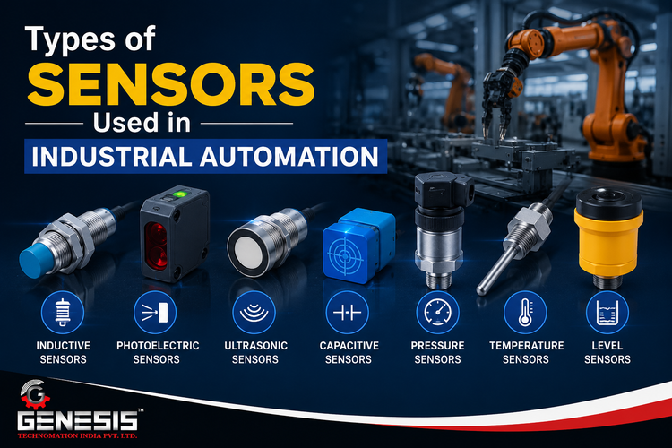
Common industrial sensors include inductive, capacitive, photoelectric, ultrasonic, laser, fiber optic, colour mark, label gap (fork), measurement, vibration, temperature, and hydrostatic level sensors.
2. Which sensor is best for detecting metal objects?
Inductive sensors are specifically designed for reliable, non-contact detection of metallic objects.
3. Can capacitive sensors detect liquids?
Yes. Capacitive sensors can detect liquids, powders, plastics, glass, and many other non-metallic materials.
4. What is the difference between photoelectric and ultrasonic sensors?
Photoelectric sensors use light for detection, while ultrasonic sensors use high-frequency sound waves. Ultrasonic sensors are often better suited for transparent or highly reflective objects.
5. Which sensor is commonly used for liquid level measurement?
Hydrostatic level sensors and ultrasonic sensors are widely used for continuous liquid level measurement, depending on the application.
6. What is a colour mark sensor used for?
Colour mark sensors detect printed registration marks and contrast differences to synchronize cutting, sealing, printing, and labeling operations.
7. Why are vibration sensors important?
They support predictive maintenance by detecting changes in machine vibration that may indicate bearing wear, imbalance, misalignment, or other mechanical issues.
8. How often should industrial sensors be maintained?
Maintenance frequency depends on the operating environment and manufacturer recommendations. Sensors in dusty, wet, or high-vibration environments typically require more frequent inspection and cleaning.
9. What factors should I consider when selecting an industrial sensor?
Key considerations include target material, sensing distance, environmental conditions, IP rating, accuracy, response time, communication interface, mounting requirements, and maintenance needs.
10. How do smart sensors support Industry 4.0?
Smart sensors provide diagnostic information, digital communication, and real-time operational data that enable predictive maintenance, process optimization, and integration with IIoT platforms.
11. Which industries rely most heavily on industrial sensors?
Automotive, pharmaceuticals, food and beverage, packaging, textile, chemical processing, water treatment, logistics, electronics, steel manufacturing, and power generation all depend extensively on industrial sensors.
12. How can sensor failures be minimized?
Proper sensor selection, correct installation, regular cleaning, preventive maintenance, periodic calibration, and adherence to manufacturer recommendations significantly improve sensor reliability and service life.
Conclusion
Understanding the Types of Sensors Used in Industrial Automation is essential for designing reliable, efficient, and future-ready manufacturing systems. From simple proximity detection to high-precision measurement and predictive maintenance, each sensor technology serves a specific purpose within an automation environment.
Selecting the right Industrial Automation Sensors requires careful evaluation of the application, operating environment, target material, sensing range, accuracy, communication requirements, and long-term maintenance considerations. A well-chosen sensor not only improves machine performance and product quality but also reduces downtime, enhances worker safety, and lowers overall operating costs.
As manufacturers continue their transition toward Industry 4.0, Smart Sensors, IIoT connectivity, AI-assisted analytics, predictive maintenance, and edge computing will become increasingly important. Organizations that invest in reliable sensor technologies today will be better positioned to improve operational efficiency, optimize asset performance, and remain competitive in the years ahead.
Whether you are building a new automation system, upgrading an existing production line, or sourcing replacement components, partnering with an experienced supplier can simplify the process. Genesis Technomation India Private Limited provides a wide range of industrial automation sensors, technical expertise, and automation solutions to support manufacturers, OEMs, and system integrators in implementing dependable and scalable industrial automation systems.
Key Takeaways
- Industrial sensors are the foundation of modern factory automation.
- Each sensor type is designed for specific detection, measurement, or monitoring tasks.
- Proper sensor selection improves productivity, quality, and equipment reliability.
- Preventive maintenance and correct installation significantly extend sensor life.
- Smart sensors and IIoT technologies are shaping the future of industrial automation.
- Choosing high-quality sensors from a trusted supplier helps ensure long-term performance and reduced lifecycle costs.
Related Posts