QS18VN6LP Photoelectric Sensor Introduction
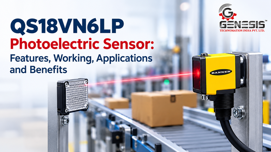
The QS18VN6LP Photoelectric Sensor is a polarized retroreflective sensor from Banner Engineering’s WORLD-BEAM QS18 series. It detects objects by monitoring light returned from a separate reflector. When an object interrupts the optical path, the sensor changes its output state, allowing a compatible controller to respond to the detection event.
The QS18VN6LP has a documented maximum sensing range of 3.5 metres, operates on a 10–30 V DC supply and uses a complementary solid-state NPN output. The standard version has a 2-metre cable. These characteristics make it a potential option for object detection in suitable industrial automation systems.
Choosing the correct sensor requires more than checking the sensing distance. Engineers must consider the target material, reflector placement, output configuration, response time, environmental conditions and compatibility with the machine controller. A mismatch in any of these areas can cause missed detections, false triggers or unreliable machine operation.
This guide covers the QS18VN6LP Photoelectric Sensor specifications, working principle, applications, benefits, installation requirements and troubleshooting considerations. It focuses on the exact model rather than assuming that every sensor in the QS18 series has identical features.
QS18VN6LP Photoelectric Sensor Overview
The QS18VN6LP is manufactured by Banner Engineering and belongs to the WORLD-BEAM QS18 family. Its detection method is polarized retroreflective sensing, which uses an emitter and receiver housed in the same sensor body and a separate reflector positioned opposite the sensor.
Unlike a diffuse-reflective sensor, which relies on light reflected directly from the target, a retroreflective sensor monitors light returned by a dedicated reflector. The object is detected when it interrupts the optical path between the sensor and reflector. This arrangement can simplify installation because only one powered sensor unit needs to be mounted and wired.
The polarized optical system is useful when objects have shiny surfaces. Polarization helps the sensor distinguish the intended reflector return from certain unwanted reflections produced by reflective targets. However, it does not guarantee reliable detection of every shiny, transparent or translucent object. Actual performance depends on the target, reflector, alignment and operating conditions.
The standard QS18VN6LP uses a cable connection and an NPN switching output. Buyers should verify these details against the complete part number on the sensor label, especially when comparing the standard cable version with models that have different connection suffixes.
QS18VN6LP Photoelectric Sensor Features and Specifications
The following table summarizes the technical information available for the QS18VN6LP.
| Parameter | Specification |
| Manufacturer | Banner Engineering |
| Product series | WORLD-BEAM QS18 |
| Model number | QS18VN6LP |
| Sensor type | Polarized retroreflective photoelectric sensor |
| Detection principle | Retroreflective optical detection with polarization |
| Maximum sensing range | 3.5 m |
| Light source | Visible red LED |
| Wavelength | 630 nm |
| Supply voltage | 10–30 V DC |
| Output configuration | Complementary solid-state NPN |
| Switching function | NO/NC functions; verify output behaviour in the manufacturer’s wiring diagram |
| Typical response time | Less than 0.6 ms |
| Maximum switching frequency | Up to 800 Hz |
| Standard connection | 2 m cable |
| Adjustment | Sensitivity potentiometer |
| Housing | Rectangular housing with M18 mounting arrangement |
| Housing material | ABS plastic |
| Lens material | Acrylic |
| Dimensions | Approximately 31 × 15 × 35 mm, with an 18 mm threaded mounting section |
| Protection rating | IP67 |
| Operating temperature | −20°C to +70°C |
| Reflector | Separate reflector required |
These specifications should be checked against the datasheet supplied for the exact model before ordering or installing the sensor.
Understanding the Main Specifications
Sensing range
The stated maximum sensing range is 3.5 metres. This is the specified optical operating capability under suitable conditions, not a guarantee that every target will be detected reliably at that distance. Reflector selection, alignment, contamination and installation geometry can affect actual performance.
Supply voltage
The sensor operates from a 10–30 V DC supply. The power supply must remain within this range during normal operation and switching. Engineers should also verify supply polarity, ripple limits and protection requirements using the manufacturer’s technical documentation.
NPN output
An NPN output typically switches the output toward the supply’s common or negative reference. PLC input compatibility depends on the input circuit, common wiring and output arrangement. Do not assume that an NPN sensor can directly replace a PNP model without checking the control system.
Response time
A typical response time below 0.6 milliseconds allows the sensor to respond rapidly to optical changes. Actual system performance also depends on the PLC scan cycle, input filtering, output circuitry, target spacing and machine mechanics.
Ingress protection
The IP67 rating indicates protection against dust ingress and temporary immersion under applicable test conditions. It does not mean that the sensor is suitable for every chemical, high-pressure washdown process or extreme industrial environment.
Sensitivity adjustment
The documented sensitivity potentiometer provides an adjustment option during setup. Make adjustments according to the manufacturer’s instructions and verify operation with the intended reflector and production targets.
Cable connection
The standard version uses a 2-metre cable. A different cable length or connection type may require another model variant, so buyers should check the full ordering code rather than selecting a sensor based only on the QS18 family name.
How the QS18VN6LP Photoelectric Sensor Works
The QS18VN6LP uses polarized retroreflective detection. The emitter and receiver are located inside the same housing, while a separate reflector returns the emitted light toward the receiver. The sensor detects an object when it interrupts this optical path.
The operating sequence is straightforward.
Light emission: The sensor emits visible red, polarized light toward the reflector.
Reflector return: The reflector returns light toward the receiver while the optical path remains clear.
Target detection: An object crossing the detection area interrupts the returned light.
Output signal: The sensor changes its electrical output state, allowing a compatible PLC or controller to process the detection event.
Machine response: The controller may use the signal to count an object, initiate a sequence or trigger another programmed action.
The actual electrical state depends on the selected output function and wiring. Engineers should consult the wiring diagram rather than infer the signal state from the presence or absence of a target.
Correct alignment is essential. The sensor and reflector must face each other, and the detection point must intersect the path followed by the target. A displaced reflector, loose mounting bracket or obstructed optical path can affect the received signal.
Detection Performance of the QS18VN6LP
The QS18VN6LP has a documented maximum sensing range of 3.5 metres. Its practical performance depends on installation conditions and the optical environment at the detection point.
Target Size, Colour and Surface
The target must interrupt enough of the optical path to produce reliable detection. A small object passing near the edge of the beam may behave differently from a large carton crossing the centre.
Target colour and surface finish can also influence the surrounding optical environment. Polarization helps distinguish the intended reflector return from some unwanted reflections, but it should not be treated as a universal solution for every reflective or transparent material.
Test the sensor with representative production objects before approving the installation. If products vary considerably in size, shape or surface properties, evaluate each relevant type.
Reflector Alignment and Sensing Distance
The sensor must receive a sufficiently strong return signal when the optical path is clear. Poor alignment, dirt on the reflector or installation near the maximum sensing distance can reduce the available optical margin.
Mount the sensor and reflector securely, then test them with the actual objects used on the production line. Verify operation at the required distance rather than relying only on the maximum range stated in the specifications.
Ambient Light and Contamination
Strong surrounding light, accumulated dust, oil or other contamination can interfere with optical sensing under certain conditions. Inspect the lens and reflector as part of routine maintenance, and evaluate the sensor under the lighting conditions present during normal production.
Machine Speed and Repeatability
The documented typical response time is below 0.6 milliseconds, and the specified switching frequency is up to 800 Hz. These values are useful when evaluating fast-moving targets, but they do not establish the maximum product-counting speed of a complete machine.
Target spacing, beam interruption duration, PLC scan time, input filtering and mechanical timing must also be considered. Test the complete system at the intended production speed before approving the installation.
Applications of the QS18VN6LP Photoelectric Sensor
The QS18VN6LP can be considered for applications that suit polarized retroreflective detection, provided the operating distance, target geometry, electrical interface and environmental requirements are compatible with its specifications.
Object Detection in Automated Machinery
The sensor can monitor whether an object crosses a defined optical path. In an automated machine, a PLC can use the resulting signal to initiate a sequence, update a counter or coordinate the next operation.
For example, an object passing through a station can interrupt the beam and provide a detection input. The control program determines what happens next.
Conveyor Systems
A sensor and reflector can be installed on opposite sides of a conveyor to detect passing cartons, packages or other suitable products.
The output may support product counting, transfer timing or detection of an occupied section. The mounting position must ensure that the object crosses the beam consistently and that conveyor vibration does not disturb alignment.
Packaging Machines
Packaging equipment often needs to detect products as they move between filling, sealing, labelling or transfer stages.
The QS18VN6LP may suit a detection point where the product reliably interrupts the beam. Engineers should confirm that the packaging material, reflector placement and production speed are appropriate. Transparent films and other optically challenging targets require particular attention during testing.
Assembly Automation
Assembly systems may use the sensor to check whether a component reaches a defined position. A compatible controller can use this event to advance a sequence or prevent the next step from starting until the required detection occurs.
The sensor confirms an optical interruption; it does not independently verify component dimensions, correct assembly or product quality.
Product Counting and Monitoring
Repeated interruptions can be counted by a PLC or other compatible controller. Successful counting depends on the duration of each interruption, spacing between products, controller input settings and the sensor’s switching performance.
Products must pass through the sensing zone in a way that produces distinct detection events. Overlapping targets or insufficient gaps may cause inaccurate counts.
Carton, Bottle and Container Detection
Cartons and many opaque containers can be suitable targets if their dimensions and travel paths allow them to interrupt the beam reliably.
Bottle detection requires additional assessment. Transparent glass or plastic may not behave like an opaque carton, and the QS18VN6LP should not be assumed to provide dependable clear-object detection without application-specific evidence and testing.
Industrial Production Lines
On a production line, the sensor may provide a discrete presence signal to a machine controller. This signal can help coordinate conveyor movement, material transfer or other automated operations.
Its suitability depends on the actual installation. It should not be treated as a safety-rated presence detector or used as a substitute for an appropriate machine-safety system.
Benefits of the QS18VN6LP Photoelectric Sensor
The QS18VN6LP offers several practical characteristics for compatible industrial detection tasks.
- Longer detection distance: Its specified maximum range of 3.5 metres allows engineers to evaluate it for applications where the sensor and reflector cannot be placed close together.
- Polarized retroreflective sensing: The optical arrangement supports detection by monitoring a returned beam and helps manage certain unwanted reflections from shiny objects.
- Single powered sensor unit: The emitter and receiver share one housing, so the reflector does not require a separate powered sensor connection.
- Fast response: The typical response time below 0.6 ms can support applications requiring rapid detection, subject to the complete system’s timing limits.
- Sensitivity adjustment: The documented potentiometer provides an adjustment option for setting up the sensor.
- Industrial environmental protection: The IP67 rating and specified operating temperature range of −20°C to +70°C support consideration in appropriate industrial environments.
These features do not guarantee a particular improvement in productivity, counting accuracy or maintenance cost. Those outcomes depend on correct selection, installation and integration.
QS18VN6LP in Industrial Automation
The QS18VN6LP provides a discrete switching signal rather than a continuous measurement of distance. Its role is to report a change in optical detection status to a compatible control system.
PLC and Machine-Controller Integration
Before connecting the sensor, confirm that the PLC input supports its NPN output configuration. Check the controller’s input circuit, common terminal arrangement, operating voltage and required signal polarity.
A controller can then use the input to execute programmed actions, such as:
- Counting passing products.
- Triggering a conveyor sequence.
- Confirming that a target has reached a detection point.
- Coordinating a pneumatic actuator.
- Starting or stopping a non-safety-related process step.
- Recording product presence for process monitoring.
Servo and Stepper Motor Systems
The sensor may provide a position-related detection event to a controller operating servo- or stepper-driven machinery. However, it is not a substitute for an encoder or a dedicated position-measurement system.
Where precise motion coordination is required, engineers must account for sensor response time, controller processing, drive response and mechanical stopping distance.
Electrical Compatibility and Wiring
The standard model is documented with a four-core, 2-metre PVC cable. Its output is NPN, and the technical documentation reports short-circuit and reverse-polarity protection.
Use the manufacturer’s wiring diagram to identify the power and output conductors. Do not rely on wire colours or pin assignments taken from a different QS18 variant. Isolate power before changing connections and verify the completed circuit before placing the machine into operation.
QS18VN6LP Installation and Mounting Considerations
Correct installation is essential for stable detection. Follow these steps when integrating the QS18VN6LP into industrial equipment.
Confirm the complete model number. Check the product label and datasheet before preparing the mounting arrangement or electrical connections. A similar model number may indicate a different output or connection type.
Position the reflector correctly. Place the reflector opposite the sensor so that the optical path crosses the intended detection point. Adjust the alignment until the sensor operates consistently.
Maintain the required sensing distance. The documented range extends to 3.5 metres. Confirm reliable operation at the actual installation distance, including under normal production conditions.
Secure the housing. Use a suitable mounting arrangement and prevent excessive vibration from moving the sensor or reflector.
Check electrical compatibility. Verify the 10–30 V DC supply, NPN output and controller input requirements. Follow the official wiring diagram for the exact model.
Protect the cable. Route the cable away from moving machinery, sharp edges and potential sources of electrical interference. Avoid excessive pulling, bending or crushing.
Test with production targets. Test the actual objects at the required speed and distance. Check both detection and recovery after the object leaves the beam.
Factors Affecting QS18VN6LP Detection
Detection problems often result from installation conditions rather than a defective sensor. The following checks can help identify common causes.
| Factor | Potential Effect | Recommended Action |
| Incorrect alignment | Weak or unstable reflector return | Align the sensor and reflector and secure their mounting |
| Excessive distance | Reduced optical margin | Test at the actual distance and adjust positioning where possible |
| Dirty lens or reflector | Reduced received light | Clean the optical surfaces using an appropriate method |
| Reflective target | Unwanted optical reflections | Test the target with the polarized sensor in its actual position |
| Transparent target | Unreliable beam interruption | Conduct application-specific tests; do not assume clear-object capability |
| Strong ambient light | Possible optical interference | Test under normal lighting and review installation geometry |
| Mechanical vibration | Changing alignment | Strengthen the mounting and inspect for movement |
| High production speed | Missed or merged detection events | Check response timing, target spacing and PLC input settings |
| Electrical incompatibility | Incorrect controller input state | Verify NPN compatibility, supply voltage and wiring |
| Electrical interference | Unstable signals | Inspect cable routing, grounding and the control cabinet layout |
These are general diagnostic considerations for the sensor’s detection principle. The appropriate corrective action depends on the symptoms and the machine’s electrical design.
QS18VN6LP Maintenance and Troubleshooting
Routine inspection helps maintain dependable operation. Check the sensor, reflector, mounting hardware, cable and controller input whenever detection becomes inconsistent.
| Problem | Possible Cause | Recommended Action |
| Object is not detected | Misalignment, contamination or unsuitable target | Inspect the optical path, target and reflector alignment |
| Detection is intermittent | Loose mounting or unstable electrical connection | Secure the mounting and inspect the connections |
| False triggering occurs | Optical interference or incorrect setup | Check alignment and test under normal lighting conditions |
| PLC does not register the output | NPN/PLC incompatibility or wiring fault | Verify the wiring diagram and PLC input configuration |
| Objects are missed at higher speeds | Insufficient interruption time or controller limitations | Review sensor response time, input filtering and product spacing |
| Detection differs between products | Variations in size, transparency or surface properties | Test representative products and adjust the installation |
| Indicator activates but the machine does not respond | PLC logic or sequence issue | Check the input status, program conditions and interlocks |
The sensor documentation identifies green power indication, yellow switching-state indication, and flashing indicator states for error and excess-gain conditions. Consult the manufacturer’s instructions to interpret these indications correctly.
Always isolate power before inspecting electrical connections. Never bypass machine interlocks or safety devices to troubleshoot a detection problem.
Why Consider QS18VN6LP for Industrial Applications?
The QS18VN6LP is worth evaluating when an application requires polarized retroreflective sensing, a maximum sensing distance of 3.5 metres and an NPN switching output.
It may be relevant to the following industrial users.
- OEMs: For integrating object detection into appropriately designed machines.
- Packaging-machine manufacturers: For detecting products at selected stages of a packaging sequence.
- Automation system integrators: For supplying discrete detection inputs to compatible control systems.
- Production engineers: For monitoring product movement and detecting objects at defined points.
- Maintenance teams: For replacing an existing sensor when its specifications and connection arrangement match the required application.
The decision should be based on technical compatibility, not the series name alone. Check the sensing principle, target properties, electrical interface, environmental limits and mechanical dimensions before selecting the model.
Where to Buy QS18VN6LP Photoelectric Sensor in India
Industrial buyers can contact Genesis Technomation India Pvt. Ltd. to enquire about photoelectric sensors and industrial automation product requirements.
Looking to buy a QS18VN6LP Photoelectric Sensor? Contact Genesis Technomation India Pvt. Ltd. to enquire about product availability, pricing, technical documentation and application suitability.
Before ordering, confirm the exact model number, output configuration, cable version and required technical specifications.
Availability, pricing and supply terms should be confirmed directly with the supplier. Contact the company through its official product page to discuss your requirements. Product availability and authorized-distributor status for this particular model should not be assumed without confirmation.
QS18VN6LP Buying Considerations
Before purchasing the QS18VN6LP, review the following checklist.
- Exact model number: Confirm QS18VN6LP rather than a PNP, connector-based or extended-cable variant.
- Detection principle: Make sure polarized retroreflective sensing suits the application.
- Sensing distance: Confirm that the required distance falls within the specified range and works reliably with the selected reflector.
- Target material: Evaluate size, colour, reflectivity and transparency.
- Machine speed: Ensure that the sensor and controller can register each detection event.
- Supply voltage: Confirm compatibility with the available 10–30 V DC supply.
- Output type: Verify NPN compatibility with the PLC or machine controller.
- Switching function: Confirm the required NO/NC behaviour and signal interpretation.
- Connection requirements: Check the cable length and conductor requirements.
- Mounting dimensions: Ensure the housing and mounting arrangement fit the machine.
- Environmental conditions: Compare the installation environment with the specified operating temperature range and IP67 rating.
- Documentation: Obtain the exact datasheet and wiring diagram before installation.
- Supplier support: Confirm availability, pricing and technical assistance before placing an order.
This checklist reduces the risk of ordering a sensor that fits mechanically but fails to meet the application’s electrical or optical requirements.
Frequently Asked Questions About QS18VN6LP
What is the QS18VN6LP Photoelectric Sensor?
The QS18VN6LP is a Banner Engineering WORLD-BEAM QS18 polarized retroreflective photoelectric sensor. It detects objects that interrupt the optical path between the sensor and a separate reflector.
How does the QS18VN6LP sensor work?
It emits polarized red light toward a reflector and monitors the returned light. When a target interrupts the beam, the sensor changes its output state, which a compatible controller can detect.
What are the main features of QS18VN6LP?
Its documented features include a 3.5-metre maximum sensing range, 10–30 V DC supply, complementary solid-state NPN output, 2-metre cable, sensitivity potentiometer and IP67 protection.
What are the specifications of QS18VN6LP?
The sensor uses visible red light at 630 nm, has a typical response time below 0.6 ms and supports a switching frequency up to 800 Hz. Its specified operating temperature range is −20°C to +70°C. Refer to the exact datasheet for complete technical details.
What are the industrial applications of QS18VN6LP?
Potential applications include conveyor detection, packaging equipment, product counting and automated assembly stations. Suitability depends on the target, reflector arrangement, production speed and controller compatibility.
What factors affect QS18VN6LP detection performance?
Alignment, sensing distance, reflector condition, target geometry, contamination, ambient light and machine speed can affect performance. Testing with actual production targets is essential.
How should QS18VN6LP be installed?
Mount the sensor and reflector opposite each other, align the optical path with the target, secure the mounting and verify the electrical connections against the manufacturer’s instructions. Test detection under normal operating conditions before commissioning.
What should I check if QS18VN6LP does not detect an object?
Inspect the reflector alignment, optical surfaces, target path, supply voltage and wiring. Check the sensor indicators and confirm that the PLC input supports the NPN output. Consult the manufacturer’s troubleshooting instructions if the issue persists.
Can QS18VN6LP be connected to a PLC?
Yes, provided the PLC input is electrically compatible with the sensor’s NPN output and the required switching function. Confirm the input circuit and wiring diagram before connecting the sensor.
Where can I enquire about QS18VN6LP price in India?
You can contact Genesis Technomation India Pvt. Ltd. to enquire about pricing, availability and technical suitability for your application. Confirm the exact model and specifications before placing an order.
Conclusion
The QS18VN6LP Photoelectric Sensor is a polarized retroreflective sensor designed for industrial object detection. Its documented specifications include a maximum sensing range of 3.5 metres, a 10–30 V DC supply, a complementary solid-state NPN output and a typical response time below 0.6 ms.
These characteristics make it a candidate for suitable conveyor, packaging, assembly and product-monitoring applications. Reliable performance still depends on reflector alignment, target properties, electrical compatibility and the timing requirements of the complete control system.
Before purchasing or installing the sensor, confirm the complete model number, review the applicable technical documentation and test the unit with actual production targets. Industrial buyers can contact Genesis Technomation India Pvt. Ltd. to enquire about product availability, pricing and technical suitability for their automation requirements.
Related Posts