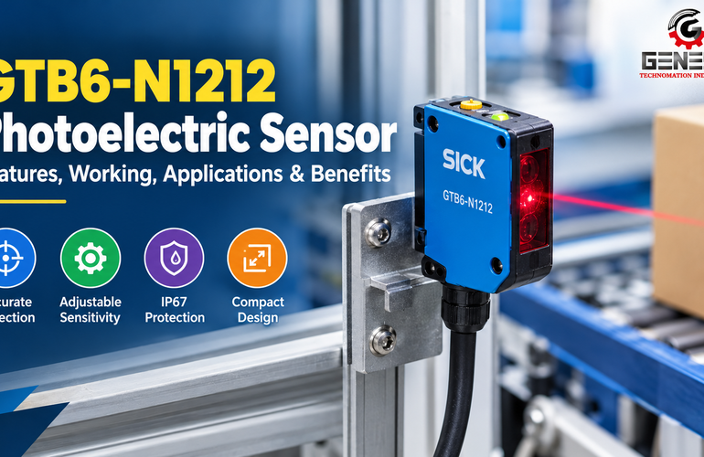
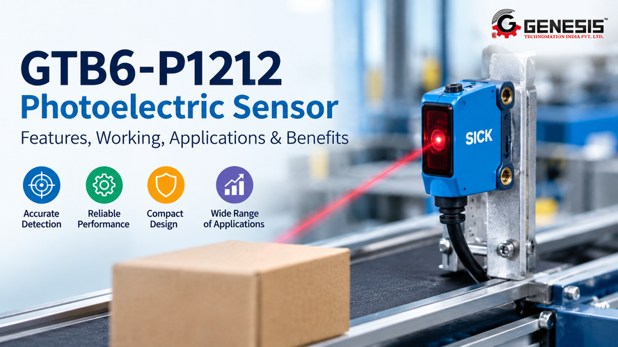
The GTB6-P1212 Photoelectric Sensor is a SICK G6 series sensor designed for reliable non-contact object detection using background suppression technology. It uses a visible red PinPoint LED to detect objects while helping distinguish them from background surfaces. With its adjustable sensing range, PNP switching output, compact design, and fast response time, this sensor can be considered for suitable applications in packaging machinery, conveyor systems, assembly lines, and industrial automation. Understanding its technical specifications, working principle, installation requirements, and benefits helps engineers and machine builders determine whether the GTB6-P1212 is the right choice for their application.
What Is the GTB6-P1212 Photoelectric Sensor?
The GTB6-P1212 is a photoelectric proximity sensor manufactured by SICK. It belongs to the G6 product family and has manufacturer part number 1052444. The sensor uses light to detect objects without making physical contact with them.
Its background suppression technology helps distinguish an intended target from objects or surfaces located behind it. This can be useful in industrial environments where a fixed machine component, conveyor structure, or background surface could otherwise affect object detection.
The GTB6-P1212 uses visible red light to identify objects within its sensing capabilities. Its PNP switching output allows it to communicate with compatible PLCs and industrial control systems.
The sensor is designed for applications that require object presence detection, product monitoring, or machine sequencing. However, engineers should evaluate the target material, sensing distance, installation geometry, and electrical requirements before selecting it for a particular machine.
GTB6-P1212 Technical Specifications
The following table summarizes the model-specific specifications used to evaluate the GTB6-P1212 for industrial applications.
| Specification | GTB6-P1212 Details |
| Manufacturer | SICK |
| Product family | G6 |
| Manufacturer part number | 1052444 |
| Sensor type | Photoelectric proximity sensor |
| Detection principle | Background suppression |
| Maximum sensing range | 5–250 mm, depending on conditions |
| Specified sensing range | 35–140 mm |
| Light source | PinPoint LED |
| Light type | Visible red light |
| Wavelength | 650 nm |
| Light spot size | Approximately 6 mm diameter at 100 mm |
| Supply voltage | 10–30 V DC |
| Output type | PNP |
| Maximum output current | 100 mA, limited to 50 mA when supply voltage exceeds 24 V |
| Response time | Less than 625 µs |
| Switching frequency | 1,000 Hz |
| Connection | Three-wire cable, 2 m |
| Housing shape | Rectangular |
| Housing material | ABS/PC plastic |
| Front screen material | PMMA plastic |
| Cable material | PVC |
| Dimensions (W × H × D) | 12 × 31.5 × 21 mm |
| Enclosure rating | IP67 |
| Operating temperature | −25°C to +55°C |
| Storage temperature | −40°C to +70°C |
| Switching mode | Selectable light/dark switching |
| Adjustment | Mechanical spindle, five turns |
| Protection class | III |
| Weight | Approximately 60 g |
The maximum sensing range and specified sensing range represent different measurements. The maximum range depends on target conditions, including reflectance. It should not be assumed that every object can be detected at the maximum distance.
The sensor also includes documented reverse-polarity protection and output overcurrent and short-circuits protection. These features help protect the device against certain electrical faults, but correct wiring and suitable circuit design remain necessary.
Key Features of the GTB6-P1212 Photoelectric Sensor
Background Suppression Technology
Background suppression is one of the main features of the GTB6-P1212. It helps the sensor distinguish an intended target from a background surface according to the sensing arrangement and adjustment.
Consider a conveyor carrying cartons past a fixed machine panel. The sensor needs to detect each carton without responding unnecessarily to the panel behind it. Background suppression can help achieve this when the target and background are positioned within the sensor’s operating capabilities.
This feature can reduce unwanted switching in suitable applications. However, it does not eliminate every influence caused by target reflectance, background distance, surface finish, or installation geometry.
PinPoint LED with Visible Red Light
The GTB6-P1212 uses a PinPoint LED that emits visible red light at a wavelength of 650 nm. Its light spot measures approximately 6 mm in diameter at a distance of 100 mm.
The visible spot makes it easier for an installer to align the sensor with the intended target. This can help during installation on packaging machines, assembly fixtures, and conveyor systems.
Correct alignment is particularly important when the sensor must detect small components or objects moving through a narrow detection area. The actual target must still be large enough and suitable for reliable detection.
Adjustable Sensing
The sensor includes a five-turn mechanical adjustment spindle. This adjustment mechanism allows the sensing configuration to be set according to the application.
Proper adjustment is important when the target passes in front of a background surface. The sensor should detect the target consistently while avoiding unwanted switching when the target is absent.
Engineers should follow the manufacturer’s adjustment instructions and test the sensor with actual production materials before commissioning.
PNP Switching Output
The GTB6-P1212 uses a PNP digital output. In a typical compatible circuit, a PNP output supplies a positive voltage signal to a connected PLC input or load when the output is active.
This output type is widely used in industrial control systems. However, a PNP sensor cannot automatically be assumed compatible with every PLC input.
Before installation, check the PLC input type, supply voltage, common wiring arrangement, input current requirements, and the sensor’s output-current limit.
Compact Housing
The sensor measures 12 × 31.5 × 21 mm. Its rectangular housing can help machine builders install it in compact equipment where mounting space is limited.
This design may be useful in packaging stations, small assembly machines, product inspection points, and conveyor guides.
The mounting position should leave enough space to access the adjustment mechanism and cable. Engineers should also consider mechanical protection and the possibility of vibration.
IP67 Enclosure Protection
The GTB6-P1212 has an IP67 enclosure rating. Under standardized test conditions, this rating indicates protection against dust ingress and temporary immersion in water.
It does not automatically make the sensor suitable for every washdown process, chemical exposure, or high-pressure cleaning environment.
The documented operating temperature range is −25°C to +55°C. The installation environment should remain within the applicable limits, with particular attention to moisture, contamination, temperature, and cable protection.
Fast Switching Response
The sensor has a specified response time of less than 625 microseconds and a switching frequency of 1,000 Hz.
These characteristics can support fast object detection on automated machinery. However, the practical performance of a complete system also depends on object spacing, conveyor speed, PLC input filtering, controller scan time, and program logic.
Machine builders should verify the complete signal path when using the sensor for counting or high-speed sequencing.
How Does the GTB6-P1212 Work?
The GTB6-P1212 working principle involves light emission, reflected-light reception, background suppression, signal processing, and output switching.
Step 1: The Sensor Emits Visible Light
The PinPoint LED sends visible red light toward the target object. The sensor is mounted so the light reaches the intended detection area.
The mounting position should account for the target’s size, movement, and orientation.
Step 2: Light Reflects from the Target
When the light reaches the target, some of it reflects toward the sensor’s optical receiving system.
The amount of returned light depends on several factors, including the target’s material, surface finish, color, angle, and distance. As a result, two objects at the same distance may not produce identical detection conditions.
Step 3: Background Suppression Evaluates the Detection Condition
The sensor evaluates the optical signal using its background suppression principle. This helps distinguish the intended target from background surfaces within the device’s operating capabilities.
For example, a carton moving along a conveyor may need to be detected while a stationary machine frame remains in the background.
Correct sensing distance and adjustment are essential for this distinction.
Step 4: Internal Electronics Process the Signal
The sensor processes the detected condition and determines the output state. The result depends on the target’s position, the sensor’s adjustment, and the selected switching mode.
If the installation is incorrect, the output may switch at an unsuitable position or fail to respond consistently.
Step 5: The PNP Output Changes State
The sensor provides a digital PNP switching signal. Its light/dark switching configuration determines the relationship between the detected light condition and the output state.
The required switching behavior should be established during installation and checked against the machine’s control logic.
Step 6: The PLC Initiates the Programmed Action
A compatible PLC receives the sensor signal and uses it as an input to the control program.
Depending on the application, the PLC may count a product, stop a conveyor, confirm part presence, or advance a machine sequence.
The sensor provides the detection signal; the controller determines the resulting machine action.
Understanding Background Suppression
Background suppression helps a photoelectric sensor distinguish an intended object from surfaces located behind it.
In some sensing arrangements, a background object can affect the received optical signal and cause unwanted switching. This may occur when products pass in front of fixed conveyor structures or machine panels.
A background suppression sensor is designed to reduce this problem under appropriate operating conditions.
For example, a packaging machine may need to detect individual cartons while ignoring the conveyor structure behind them. Properly selected and adjusted background suppression can help the machine identify the cartons at the intended position.
Several factors influence the result:
- Target distance: The object should pass within the suitable sensing range.
- Target reflectance: Dark and bright materials may produce different optical responses.
- Background position: The distance between the target and background can affect discrimination.
- Target geometry: Small, irregular, or angled surfaces may be more difficult to detect consistently.
- Adjustment: Incorrect adjustment can cause unwanted switching or missed detection.
- Installation conditions: Vibration, contamination, and alignment errors may affect performance.
Background suppression does not make a sensor completely independent of target characteristics. Testing the real target and background combination is necessary before using the device in production.
GTB6-P1212 Sensing Range and Detection Performance
The GTB6-P1212 has a specified sensing range of 35–140 mm and a maximum sensing range of 5–250 mm, depending on conditions.
These figures should not be treated as interchangeable.
The specified sensing range provides a practical starting point for evaluating a typical installation. The maximum sensing range describes the broader detection capability under defined reference conditions. Actual performance depends on the target and the installation.
Factors That Affect Sensing Range
Target reflectance: Dark surfaces may return less light than bright surfaces. This can affect the distance at which an object is detected.
Target color: Color can influence reflectance, although color alone does not determine whether a target can be detected.
Surface finish: Matte, glossy, rough, and textured materials reflect light differently. The sensor should be tested with the actual surface.
Target size and shape: A small or irregular component may not provide a consistent detection surface. Its orientation may also affect the signal.
Background position: A background that is too close to the target or arranged unfavorably may affect detection performance.
Sensor alignment: Incorrect alignment can cause the sensing spot to miss the target or fall on an unintended surface.
Contamination: Dust, oil, or residue on the optical surface may interfere with the optical system.
Ambient conditions: Lighting, temperature, and environmental contamination should be considered within the manufacturer’s documented operating limits.
Mechanical vibration: Movement of the sensor or target can change the sensing geometry and cause inconsistent switching.
For reliable operation, engineers should select a suitable working distance and test the sensor with representative production materials. Do not assume that every target can be detected at 250 mm.
Industrial Applications of the GTB6-P1212
The GTB6-P1212 can be considered for applications requiring non-contact object detection, background suppression, and a compatible PNP output.
Its suitability depends on the target, installation distance, environmental conditions, and control-system requirements.
Packaging Machinery
Packaging machines often need to detect cartons, trays, containers, or packaged products at specific positions.
The GTB6-P1212 may be used to detect a carton as it reaches a filling, sealing, labeling, or transfer station. The sensor sends a switching signal to the PLC, which can use that signal to coordinate the next operation.
For example, the controller may wait for a carton to reach the correct position before activating a mechanism.
The target material should be tested, particularly when the packaging has dark printing, glossy surfaces, or irregular geometry.
Conveyor Systems
Conveyor systems use object detection to monitor products moving between stations.
The sensor may detect an item approaching a transfer point or confirm that a product has reached a defined location. The PLC can use the signal to control conveyor movement or coordinate another machine.
Correct placement is important when products are close together. Engineers should check the actual conveyor speed, object spacing, and controller response.
Assembly Machines
Assembly machines often need to confirm the presence of a component before performing the next operation.
The GTB6-P1212 may be evaluated for detecting a part in a fixture or confirming that an object has reached an assembly station.
The target’s size, reflectance, and orientation should be considered. Very small components or objects with challenging surfaces may require a different sensor or sensing arrangement.
Material Handling Equipment
Automated material handling systems move components and products between processing stations, storage locations, and transfer points.
The sensor may detect an object at a defined position and send the signal to a machine controller. The controller can then coordinate a transfer or update the process sequence.
It should not be treated as a replacement for a dedicated safety-rated sensor where personnel protection is required.
Manufacturing and Production Lines
On a manufacturing line, the GTB6-P1212 may provide a product-presence signal to support process monitoring.
For example, a PLC may check whether a component has arrived at a workstation before activating an actuator. If the expected signal is missing, the control program can prevent the next step or initiate a fault response.
The exact behavior depends on the machine’s control logic and risk assessment.
Product Counting and Position Detection
A PLC can count sensor transitions as products pass through the detection area.
The sensor’s response time and switching frequency can support suitable counting applications, but successful counting also depends on object spacing, conveyor speed, and PLC input processing.
If products pass too closely together, the system may miss individual transitions. Commissioning should therefore include tests at the intended production speed.
OEM Machinery
Original equipment manufacturers can evaluate the GTB6-P1212 for compact machine designs requiring background suppression and PNP output.
Before standardizing it across a machine platform, the OEM should confirm:
- Target and background compatibility.
- Sensing distance and mounting arrangement.
- PLC input compatibility.
- Environmental requirements.
- Access for adjustment and maintenance.
- Availability of replacement units.
- Total cost over the expected machine life.
Testing representative products is particularly important when the machine handles different materials, colors, or sizes.
Benefits of the GTB6-P1212 Photoelectric Sensor
The sensor offers several practical benefits when selected and installed correctly.
Non-Contact Object Detection
The sensor detects objects without needing to touch them. This can help avoid mechanical contact with products and supports automated detection in moving machinery.
Background Suppression
Background suppression can help distinguish the intended target from surfaces behind it, reducing unwanted switching in suitable installations.
Visible Light for Alignment
The visible red PinPoint LED helps installers locate the sensing spot and align the sensor with the intended detection area.
Adjustable Sensing
The mechanical adjustment mechanism allows the sensor to be configured according to the target and background arrangement.
PNP Output for Compatible Control Systems
The PNP digital output can integrate with compatible PLC inputs and industrial control equipment.
Compact Installation Dimensions
The compact rectangular housing can help machine builders install the sensor in space-constrained locations.
Fast Switching Response
The response time below 625 µs can support fast detection tasks when the overall control system is designed to process the signal correctly.
Industrial Enclosure Protection
The IP67 rating provides documented dust and temporary-immersion protection under standardized conditions. Environmental suitability must still be checked for the specific installation.
Electrical Protection Features
Documented reverse-polarity, output overcurrent, and short-circuit protection help protect the sensor against certain electrical faults.
Potential Reduction in Unwanted Switching
Correct selection and adjustment can reduce unwanted switching caused by background surfaces in suitable applications. The result should be verified through commissioning tests.
No sensor guarantees perfect detection under every condition. Proper application engineering remains essential.
GTB6-P1212 PLC Integration
The GTB6-P1212 can provide a digital signal to a compatible programmable logic controller.
The typical signal path is:
Target Object → GTB6-P1212 → PNP Output → PLC Input → Machine Action
When the target enters the sensing area, the sensor changes its output state according to the detection condition and selected switching mode. The PLC receives the signal and evaluates it through the control program.
Potential control functions include:
- Product-presence detection.
- Conveyor start or stop logic.
- Product counting.
- Assembly verification.
- Machine sequencing.
- Transfer-point monitoring.
- Fault detection when an expected product signal is missing.
Electrical Compatibility
Before installation, verify the supply voltage, PLC input type, input current requirements, common wiring, and sensor output-current limit.
The sensor’s maximum output current is 100 mA, reduced to 50 mA when the supply voltage exceeds 24 V. The load must remain within the applicable limit.
Use the official connection diagram for the GTB6-P1212 rather than assuming pin assignments or wire colors from another sensor.
The control program should also account for the selected light/dark switching mode. Incorrect configuration may cause the PLC to interpret target-present and target-absent conditions differently from what the machine requires.
Installation and Adjustment Guidelines
Correct installation is essential for reliable sensing performance.
Sensor Positioning
Mount the sensor so its optical axis faces the intended target. Ensure the object enters the sensing area consistently and that nearby machine structures do not interfere with detection.
Sensing Distance
Choose a suitable working distance based on the manufacturer’s sensing-range information and the target’s characteristics.
Do not assume the maximum range will be available for every material or surface finish.
Background Suppression Adjustment
Adjust the sensor according to the manufacturer’s operating instructions. Use the actual production target and background when setting up the detection condition.
Test the sensor with the target present and absent. The background alone should not produce an unwanted switching state.
Mechanical Mounting
Secure the sensor with an appropriate bracket and mounting arrangement. Avoid excessive vibration and ensure that the sensing geometry remains stable during normal machine operation.
Leave enough space to access the adjustment mechanism and cable.
Electrical Wiring
Isolate the relevant power source where required before carrying out installation or maintenance. Confirm that the supply voltage, PNP output, PLC input, and load are compatible.
Follow the official wiring diagram and protect the cable from abrasion, crushing, and other mechanical damage.
Environmental Conditions
Operate the sensor within its documented temperature range of −25°C to +55°C. Check the installation for dust, moisture, chemicals, vibration, and possible contamination of the optical surface.
The IP67 rating should not be interpreted as universal protection against all industrial cleaning methods or chemical exposure.
Commissioning Tests
Before putting the machine into continuous production:
- Confirm the sensor’s mounting position and working distance.
- Test detection with representative production targets.
- Confirm that background surfaces do not cause unwanted switching.
- Verify the selected switching mode.
- Check the PLC input response.
- Test at the intended production speed.
- Confirm reliable operation during normal machine movement.
Document the final adjustment and configuration where required by the machine’s maintenance process.
Common Factors Affecting Performance
Several installation and operating issues can cause inconsistent detection.
| Issue | Possible Cause | Recommended Action |
| Target is not detected | Incorrect alignment or unsuitable sensing distance | Check the position and working distance |
| Background causes unwanted switching | Incorrect adjustment or unsuitable target/background arrangement | Recheck the setup using the actual target and background |
| Detection is intermittent | Vibration, contamination, or unstable target position | Inspect the mounting, optical surface, and target movement |
| PLC does not receive the signal | Wiring or PNP input incompatibility | Check the wiring diagram and PLC input specifications |
| Output does not switch as expected | Incorrect switching mode, supply voltage, or connections | Verify configuration and electrical conditions |
| Different materials produce different results | Reflectance or geometry differences | Test each relevant material and optimize the installation |
| Sensor appears inactive | Power supply or wiring fault | Check supply voltage and connections safely |
Troubleshooting should follow the manufacturer’s instructions and appropriate electrical safety procedures. Avoid changing several settings at once without identifying the underlying cause.
Maintenance Recommendations
Regular inspection helps identify problems before they affect production.
Visual Inspection
Check the housing, mounting bracket, cable, and optical surface for visible damage or contamination.
Optical Surface Cleaning
Clean the front screen using a suitable method that will not damage the optical surface. Avoid abrasive materials or cleaning agents that are incompatible with the housing.
Mounting Stability
Check that the sensor has not shifted due to vibration, impact, or maintenance work. A small change in alignment can affect detection.
Cable and Connection Inspection
Look for damaged insulation, loose connections, crushed cable sections, or signs of moisture ingress. Correct any faults using appropriate procedures.
Sensing Distance and Adjustment
Verify that the target is detected at the required position and that the background does not cause unwanted switching. Check adjustment settings if performance changes.
PLC Input Verification
Confirm that the sensor output reaches the PLC and that the control program responds as intended.
Maintenance frequency should depend on the environment, operating conditions, and manufacturer’s instructions. Installations exposed to heavy dust or contamination may require more frequent inspection.
GTB6-P1212 for OEMs and Machine Builders
OEMs must consider both the sensor’s technical performance and its suitability for the complete machine design.
The GTB6-P1212 may be suitable where the machine requires a compact photoelectric proximity sensor with background suppression and a PNP output.
Important design considerations include:
- Installation space: Confirm that the housing and cable fit the intended location.
- Sensing distance: Check that the actual target can be detected consistently.
- Background suppression: Evaluate the target and background arrangement.
- Electrical compatibility: Verify the PLC input, supply voltage, and output-current limits.
- Switching response: Match the sensor to the product speed and spacing.
- Mechanical mounting: Prevent vibration and unintended movement.
- Cable routing: Protect the cable against abrasion and mechanical damage.
- Environmental conditions: Check temperature, moisture, dust, and chemical exposure.
- Maintenance access: Allow room for cleaning, adjustment, and replacement.
- Replacement planning: Document the exact part number and relevant electrical requirements.
- Total cost of ownership: Consider installation, maintenance, replacement, and potential downtime.
Testing the sensor with actual production targets is important before standardizing it across multiple machines. A successful installation with one product does not automatically establish suitability for every material or geometry handled by the machine.
GTB6-P1212 vs Generic Photoelectric Sensors
The GTB6-P1212 should be compared with alternative photoelectric sensors according to the application’s actual requirements.
| Selection Criterion | GTB6-P1212 | What to Check in Alternatives |
| Detection principle | Background suppression | Whether another sensing principle is more suitable |
| Sensing range | Specified range of 35–140 mm; maximum range 5–250 mm | Range under comparable target conditions |
| Light source | Visible red PinPoint LED | Wavelength and alignment requirements |
| Output type | PNP | PNP, NPN, relay, or other output needs |
| Adjustment | Mechanical spindle, five turns | Adjustment method and ease of setup |
| Dimensions | 12 × 31.5 × 21 mm | Available mounting space |
| Enclosure rating | IP67 | Required environmental protection |
| Switching frequency | 1,000 Hz | Required detection rate |
| Electrical protection | Documented reverse-polarity and output overcurrent/short-circuit protection | Specific protection functions |
| Cost | Requires a current quotation | Purchase price, installation, maintenance, and replacement costs |
A different model may be preferable if the application requires a longer range, another output type, a smaller detection spot, a different sensing principle, or special environmental approvals.
The correct choice depends on the detection task, installation conditions, controller compatibility, and overall cost. Brand alone should not determine the selection.
How to Select the Right Photoelectric Sensor
Before purchasing a photoelectric sensor, review the following requirements.
1. Required Detection Method
Decide whether the application requires background suppression, diffuse sensing, retro-reflective sensing, through-beam detection, or another technology.
The GTB6-P1212 is a proximity sensor with background suppression.
2. Sensing Distance
Measure the distance between the sensor and the intended target. Confirm that the working distance falls within a suitable range for the actual material.
3. Target Material and Reflectance
Consider the target’s color, surface finish, shape, and size. Test representative samples where material variations are expected.
4. Background Conditions
Determine whether fixed surfaces or other objects behind the target could interfere with detection. Evaluate whether background suppression is suitable for the arrangement.
5. Output Type
Check whether the control system requires a PNP or NPN signal. The GTB6-P1212 uses a PNP output.
6. Supply Voltage
Confirm that the available DC supply meets the sensor’s 10–30 V requirement and all applicable electrical conditions.
7. Switching Speed
Compare the sensor’s response time and switching frequency with the target speed, spacing, and PLC input processing.
8. Installation Space
Check the housing dimensions, cable routing, mounting arrangement, and maintenance access.
9. Environmental Protection
Confirm the required enclosure rating and operating temperature. Check for dust, moisture, chemicals, vibration, and cleaning requirements.
10. PLC Compatibility
Verify input type, input current, common wiring, and output-current limits before installation.
11. Certifications and Documentation
Review the documentation and approvals required for the machine and its operating environment. Do not assume that one sensor meets every industry-specific requirement.
12. Availability and Total Cost
Confirm current stock status, price, delivery time, and replacement arrangements. Include installation and maintenance costs when comparing alternatives.
The GTB6-P1212 is worth evaluating when its sensing range, background suppression, PNP output, and environmental characteristics match the application. If these conditions are not met, another sensor or sensing technology may be more appropriate.
GTB6-P1212 Price in India
The GTB6-P1212 price in India depends on the supplier’s quotation, product availability, order quantity, shipping, taxes, delivery requirements, and any project-specific needs.
A current, independently verified market price is not provided here. Publishing an unverified rupee amount could mislead buyers because quotations and availability can change.
When requesting a quotation, provide the following information:
- Model: GTB6-P1212.
- Manufacturer part number: 1052444.
- Required quantity.
- Delivery location in India.
- Required delivery schedule.
- Any project-specific documentation or support requirements.
Compare quotations for the same model and configuration. An overseas listing may exclude shipping, taxes, import-related charges, and other costs associated with delivery in India.
Where to Buy GTB6-P1212 Photoelectric Sensor in India
Businesses looking for industrial photoelectric sensors can enquire with Genesis Technomation India Pvt. Ltd. about their sensing requirements and suitable automation products.
Visit the Genesis Technomation website or explore its photoelectric sensor product page for information about industrial sensing solutions.
Before placing an order, confirm the exact model number, current availability, price, delivery schedule, and technical suitability with the supplier. Product availability and authorized distributor status should be verified directly rather than assumed.
If you are evaluating the GTB6-P1212 Photoelectric Sensor for an industrial automation project, contact Genesis Technomation India Pvt. Ltd. to discuss your sensing requirements and product enquiry.
FAQs about GTB6-P1212 Photoelectric Sensor
What is the GTB6-P1212 Photoelectric Sensor?
The GTB6-P1212 is a SICK G6 series photoelectric proximity sensor that uses background suppression and visible red light to detect objects without physical contact. Its manufacturer part number is 1052444.
Who manufactures the GTB6-P1212?
SICK manufactures the GTB6-P1212. It belongs to the company’s G6 photoelectric sensor family.
What is the sensing principle of the GTB6-P1212?
The sensor uses photoelectric proximity detection with background suppression. This helps distinguish an intended target from background surfaces within its operating capabilities.
What is background suppression?
Background suppression helps a photoelectric sensor distinguish an intended target from surfaces behind it. Its effectiveness depends on factors such as sensing distance, reflectance, adjustment, and installation geometry.
What is the maximum sensing range of the GTB6-P1212?
The maximum sensing range is listed as 5–250 mm, depending on conditions. The achievable range varies with target characteristics and the manufacturer’s reference conditions.
What is the specified sensing range of the GTB6-P1212?
The specified sensing range is 35–140 mm. Engineers should consult the manufacturer’s sensing-range information and test the actual target before finalizing an installation.
What supply voltage does the GTB6-P1212 require?
The sensor requires a supply voltage of 10–30 V DC. The power supply must also meet the manufacturer’s electrical requirements.
What type of output does the GTB6-P1212 use?
It uses a PNP digital output with selectable light/dark switching. The maximum output current is 100 mA, reduced to 50 mA when the supply voltage exceeds 24 V.
What light source does the GTB6-P1212 use?
The sensor uses a PinPoint LED that emits visible red light at a wavelength of 650 nm. The light spot is approximately 6 mm in diameter at 100 mm.
Can the GTB6-P1212 connect to a PLC?
Yes. It can connect to a compatible PLC digital input. Check the input type, supply voltage, output-current limit, common wiring, and official connection diagram before installation.
What applications are suitable for the GTB6-P1212?
Potential applications include product detection on conveyors, carton detection on packaging machines, part-presence verification on assembly equipment, and object detection on manufacturing lines. Suitability depends on the target and operating conditions.
How do you adjust the GTB6-P1212?
The sensor uses a five-turn mechanical adjustment spindle. Follow the manufacturer’s instructions and adjust the sensing configuration using the actual target and background. Test both detection and non-detection conditions before commissioning.
What causes false or inconsistent detection?
Possible causes include incorrect sensing distance, improper adjustment, target reflectance differences, poor alignment, contamination, vibration, unstable wiring, or PLC input incompatibility. Inspect the installation and investigate each potential cause systematically.
What factors affect the GTB6-P1212 price in India?
Supplier quotation, product availability, order quantity, taxes, shipping, delivery location, and project requirements can affect the final price. Request a current quotation rather than relying on an unverified online listing.
Where can I enquire about the GTB6-P1212 in India?
You can contact Genesis Technomation India Pvt. Ltd. through its official website or visit its photoelectric sensor product page. Confirm availability, pricing, and technical suitability before ordering.
Conclusion
The GTB6-P1212 Photoelectric Sensor is a SICK G6 series proximity sensor designed for object detection using background suppression. Its documented characteristics include a specified sensing range of 35–140 mm, visible red PinPoint LED, adjustable sensing, PNP output, response time below 625 µs, and IP67 enclosure protection.
These features make it worth evaluating for suitable packaging, conveyor, assembly, and manufacturing applications. Reliable operation depends on the target material, sensing distance, background position, adjustment, and compatibility with the connected PLC.
Before purchasing, review the model’s technical specifications, confirm electrical requirements, test the actual application, and request a current quotation. For industrial sensor and automation enquiries, contact Genesis Technomation India Pvt. Ltd. through its website.
Related Posts