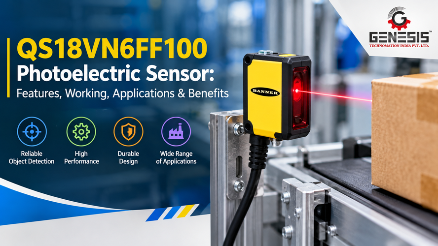
The QS18VN6FF100 Photoelectric Sensor is a Banner Engineering WORLD-BEAM QS18 Series sensor designed for industrial object detection using fixed-field background suppression. Its published product information identifies a 100 mm cutoff range, a visible red LED sensing beam, a complementary solid-state NPN output, and a 2 m cable connection. These characteristics make it a potential option for applications that require detection of parts or products at a defined position on automated machinery.
In industrial automation, dependable object detection helps machines coordinate movement, control production sequences, monitor product flow, and reduce the need for manual inspection. Selecting the correct sensor requires more than checking its detection distance. Engineers must also consider the target material, background conditions, electrical interface, installation position, and environmental requirements.
This guide covers the QS18VN6FF100’s documented specifications, working principle, industrial applications, installation, maintenance, troubleshooting, and purchasing considerations. It distinguishes verified product details from general engineering guidance so that machine builders and maintenance teams can evaluate the sensor without confusing it with similar QS18 models.
What Is the QS18VN6FF100 Photoelectric Sensor?
The QS18VN6FF100 belongs to Banner Engineering’s WORLD-BEAM QS18 Series of general-purpose photoelectric sensors. The manufacturer’s product listing identifies it as a fixed-field sensor that uses background suppression for proximity detection. Its published cutoff distance is 100 mm, or approximately 4 inches.
Unlike a mechanical limit switch, which detects contact or physical movement of an actuator, a photoelectric sensor uses light to detect a target. This allows it to monitor passing products and machine components without requiring the detected object to press against a switch.
The fixed-field background-suppression configuration is particularly relevant when a machine must detect an object in a defined area while reducing the influence of objects behind the intended target. Actual performance depends on the target, its position, the background, and the installation conditions.
The manufacturer’s documentation identifies the following characteristics for the QS18VN6FF100:
- Product family: Banner Engineering WORLD-BEAM QS18 Series.
- Sensing technology: Fixed-field photoelectric sensing with background suppression.
- Sensing beam: Visible red LED, with a listed wavelength of 630 nm.
- Published cutoff distance: 100 mm.
- Output: Complementary solid-state NPN.
- Supply voltage: 10–30 V DC.
- Connection: 2 m cable.
- Housing: Rectangular design with an M18 mounting arrangement.
- Ingress protection: IP67.
These details provide a starting point for determining whether the sensor is compatible with a particular machine. The official datasheet and product manual should remain the final references for installation and electrical integration.
QS18VN6FF100 Model Identification
Correct model identification matters because Banner Engineering offers several QS18 sensors with different sensing methods, distances, and output configurations.
The QS18VN6FF100 is specifically listed as a fixed-field model with a 100 mm cutoff and an NPN output. It should not be treated as interchangeable with the QS18VP6FF100, which has a different output configuration, or with diffuse-mode models such as QS18VN6D. The QS18 Series manual lists these as distinct variants.
When ordering a replacement or specifying a sensor for a new machine, check the complete model number on the existing device, the machine’s electrical drawings, and the manufacturer’s documentation. A similar-looking sensor may not provide the required switching behavior or detection characteristics.
Key Features of the QS18VN6FF100 Photoelectric Sensor
The QS18VN6FF100 has several documented characteristics that matter when selecting a photoelectric sensor for a machine or production line.
1. Fixed-field background suppression
The sensor uses fixed-field background suppression. This sensing arrangement is designed to detect objects within a defined field while suppressing the influence of background objects beyond the cutoff point.
For example, a machine builder may want to detect a small component passing in front of a mounting plate. Background suppression can help distinguish the component from the plate, although the result depends on the relative distance, reflectivity, size, and position of both surfaces.
The specified 100 mm cutoff should not be interpreted as a guarantee that every object will be detected under every condition.
2. Visible red LED sensing beam
Banner Engineering specifies a visible red LED with a wavelength of 630 nm.
A visible sensing beam can help technicians identify the sensor’s approximate sensing direction during setup. It can also make it easier to position a target in the intended detection area.
However, the visible beam does not eliminate the need to check detection stability with the actual production target.
3. NPN output configuration
The manufacturer’s listing identifies a complementary solid-state NPN output.
NPN outputs are commonly used with compatible industrial control inputs. Before connecting the sensor to a PLC, engineers should verify the input circuit, output current requirements, common wiring, and expected switching behavior.
Do not assume that a sensor with an NPN output can directly replace a PNP model. The control system must support the selected output configuration.
4. 10–30 V DC supply
The documented operating supply range is 10–30 V DC.
This range allows the sensor to be considered for compatible industrial DC control systems. During installation, check the voltage at the sensor terminals rather than relying only on the power supply’s rated output. Voltage drops, incorrect wiring, or a shared supply fault can cause unreliable operation.
5. Cable connection
The QS18VN6FF100 is listed with a 2 m cable.
A cable connection can simplify installation where the control cabinet or junction point is within reach. Machine designers should plan the cable route carefully, protect it from abrasion and moving equipment, and allow suitable strain relief.
6. Industrial housing and ingress protection
The manufacturer’s product information identifies an ABS housing, a rectangular body with an M18 mounting arrangement, and IP67 ingress protection.
IP67 indicates protection against dust ingress and temporary immersion under the standardized test conditions. It does not mean the sensor is suitable for every chemical, high-pressure washdown process, or extreme environment. The product listing does not identify this model as chemical-resistant or washdown-rated.
7. Response and operating characteristics
The manufacturer’s published specifications include a 0.85 ms output response time, a 100 ms power-up delay, and repeatability of 160 µs. The listed operating temperature range is −20°C to +70°C.
These values help engineers evaluate the sensor’s suitability for a machine’s timing and environmental requirements. Actual application performance still depends on the sensing target, installation, controller logic, and electrical interface.
QS18VN6FF100 Technical Specifications
The following table summarizes the specifications published for the exact QS18VN6FF100 model.
| Specification | QS18VN6FF100 |
| Manufacturer | Banner Engineering |
| Product family | WORLD-BEAM QS18 Series |
| Sensor type | Photoelectric sensor |
| Sensing mode | Proximity |
| Detection method | Fixed-field background suppression |
| Published cutoff distance | 100 mm (approximately 4 in) |
| Light source | Visible red LED |
| Wavelength | 630 nm |
| Output | Complementary solid-state NPN |
| Supply voltage | 10–30 V DC |
| Connection | 2 m cable |
| Housing style | Rectangular with M18 mounting arrangement |
| Housing material | ABS |
| Lens material | Acrylic |
| Ingress protection | IP67 |
| Output response time | 0.85 ms |
| Power-up delay | 100 ms |
| Repeatability | 160 µs |
| Operating temperature | −20°C to +70°C |
| Maximum listed relative humidity | 95% at 50°C |
| Indicators | LEDs |
| Adjustment | None listed |
| Clear-object detection feature | No |
| IO-Link | No |
| Exact overall dimensions | Confirm in the manufacturer’s drawing |
| Current price in India | Request a quotation |
Engineering note: Confirm the exact product drawing, electrical ratings, and applicable regional certifications before finalizing a design. Manufacturer listings for region-specific part numbers may show different regulatory or environmental classifications, so avoid transferring such details from a related variant.
QS18VN6FF100 Working Principle
The QS18VN6FF100 detects objects using fixed-field photoelectric sensing with background suppression. Its visible red LED provides the sensing beam, and its internal electronics process the optical response to determine whether a target is present within the intended detection field.
The process can be understood in the following stages.
Step 1: The sensor produces a sensing beam
The sensor emits visible red light from its LED. The optical system establishes the field in which the sensor evaluates a target.
Step 2: An object enters the detection area
When a component, package, or other suitable target enters the sensing field, the optical response changes according to the target’s properties and position.
Step 3: The sensor evaluates the target against the background
Fixed-field background suppression is intended to distinguish objects within the defined detection field from background objects beyond the cutoff point. Target reflectivity, geometry, distance, and background characteristics influence the result.
Step 4: Internal electronics process the signal
The sensor’s internal circuitry evaluates the optical signal and determines the output state. The model’s documented output is complementary solid-state NPN.
Step 5: The control system receives the output
A compatible PLC input or machine controller reads the switching state. The exact electrical connection and logic depend on the sensor’s official wiring instructions and the control-system design.
Step 6: The machine executes its programmed action
The controller may increment a counter, permit a packaging cycle, initiate a sorting sequence, or stop a conveyor when the programmed conditions are met.
The sensor itself does not decide the machine’s overall operation. It provides an input that the control program interprets.
Detection Performance: Factors Engineers Should Check
Even a correctly selected photoelectric sensor can produce inconsistent results if the installation is poorly designed.
- Target size: Small components may occupy only part of the sensing field. Test the smallest expected target, not just a large sample.
- Target color: Different colors can produce different optical responses. Validate dark, light, and mixed-color products where applicable.
- Surface finish: Glossy, polished, textured, and matte surfaces may behave differently under illumination.
- Detection distance: Keep the target within the intended operating field and verify performance at the actual mounting distance.
- Background: A nearby surface can affect detection. Test the target against the real machine structure rather than an isolated sample.
- Alignment: Position the sensing face so the intended target enters the sensing field consistently.
- Ambient light: Strong or changing light can affect some optical installations. Test under normal production lighting.
- Contamination: Dust, oil, and residue on the sensing surface can weaken or alter the optical signal.
- Vibration: A loose bracket can change the detection position and cause intermittent switching.
- Object speed: The machine’s cycle time must account for sensor response, PLC input filtering, scan time, and output-actuation delays.
- Electrical noise: Poor cable routing or grounding can interfere with control signals. Follow the manufacturer’s wiring instructions and sound industrial wiring practices.
A practical validation test should use representative production parts, the real background, the expected speed, and normal environmental conditions. Test both the presence and absence of a target before releasing the machine for operation.
QS18VN6FF100 Applications in Industrial Automation
The following are potential applications based on the sensor’s documented fixed-field, 100 mm cutoff configuration. Suitability must be confirmed against the target and installation requirements.
Packaging machinery
The sensor may be used to detect cartons, packages, or components at a defined point on a packaging machine. A PLC can use the signal to coordinate indexing, sealing, or the next process step.
For example, a machine can check whether a carton has reached a loading position before activating a downstream sequence. Engineers should verify that the carton surface and background provide stable detection.
Conveyor systems
On a conveyor, the sensor may detect products approaching a transfer point or a station where another operation begins. The controller can use the signal for product counting, transfer timing, or accumulation logic.
The mounting arrangement should keep the sensing area clear of conveyor hardware that could affect the background-suppression behavior.
Part presence detection
Assembly machinery often requires confirmation that a component has reached a fixture before a press, clamp, or other mechanism proceeds.
The QS18VN6FF100 may be suitable when the component passes through the sensor’s intended field and the surface characteristics permit reliable detection. It should not be treated as proof that a part is correctly assembled unless the system’s sensing arrangement actually verifies that condition.
Material handling
Automated material-handling equipment can use photoelectric sensors to monitor the arrival of objects at transfer positions. The sensor signal can support sequencing between conveyors, guides, and processing stations.
The 100 mm cutoff makes the actual mounting geometry particularly important. Applications requiring longer detection distances may need a different sensor configuration.
Automated production lines
A production line may use the sensor to detect a product before a workstation starts its programmed cycle. This can reduce reliance on manual confirmation and help synchronize operations.
For reliable results, the sensor must be installed where the target’s position is repeatable and where unintended background objects are unlikely to trigger the output.
Counting and position monitoring
A compatible controller can count switching events as products pass a detection point. It can also use the sensor output as one input in a position-monitoring sequence.
For counting applications, the spacing between products and the total system response must allow each object to produce a distinct, readable event. Test the complete system at maximum production speed.
Benefits of the QS18VN6FF100 Photoelectric Sensor
The model’s documented features offer several potential advantages when they match the application.
Non-contact object detection: The sensor can detect suitable targets without a mechanical actuator touching the object. This is useful when contact could interfere with product movement.
Background suppression: The fixed-field sensing arrangement is intended to reduce the influence of objects beyond the cutoff point. This can help when a target must be distinguished from a nearby background.
Visible sensing beam: The red LED can assist with setup and alignment.
Compact mounting arrangement: The rectangular housing with M18 mounting facilitates consideration for machine layouts that accommodate this mounting style.
Industrial protection: The IP67 rating supports use in environments where dust and temporary water exposure are relevant, provided the complete installation meets the required conditions.
Control-system integration: The NPN output and 10–30 V DC supply allow integration with compatible industrial control hardware.
Defined response characteristics: The published response time gives engineers a starting point for evaluating timing requirements.
These benefits are conditional, not universal guarantees. Correct selection, commissioning, and maintenance determine whether the sensor performs reliably in a specific machine.
QS18VN6FF100 in a PLC-Based Automation System
A typical integration follows this signal path:
Object → Sensor → Electrical output → PLC/controller → Programmed machine action
The sensor detects a target and changes its output state. A compatible PLC input reads that state and executes the relevant logic.
Possible uses include:
- Product-present checks before a machine cycle.
- Counting items moving through a defined detection point.
- Conveyor transfer sequencing.
- Part-arrival monitoring at assembly stations.
- Process status indications on an HMI.
- Interlocking a production step with a required detection signal.
Before connecting the QS18VN6FF100, verify that the PLC input supports the sensor’s NPN output. Confirm the required common connection, permissible input voltage, output loading, and wiring details using the manufacturer’s documentation. Do not infer cable wire colors or pin assignments from another QS18 model.
An HMI may display the PLC’s interpretation of the sensor signal, but the sensor does not provide IO-Link communication according to the published specifications.
Installation Guidelines for QS18VN6FF100
Correct installation is essential for dependable detection. Follow the official product manual for exact mounting and wiring requirements.
Sensor positioning and alignment
Mount the sensor so that the intended object enters its detection field at a repeatable position. Keep the sensing face clear of brackets, guards, and other objects that could interfere with the optical field.
Because this is a fixed-field sensor, test its response against the actual background. Do not assume that a sensor will behave identically when installed at different distances or angles.
Target position and orientation
Check how the target approaches the sensor. If a product moves, tilts, or changes orientation during production, its optical response may change. Where necessary, use a mechanical guide to keep the product in a consistent detection position.
Mounting and vibration
Secure the mounting arrangement using the hardware and installation method specified by the manufacturer. Check for vibration caused by motors, conveyors, presses, and other machinery.
Avoid tightening hardware in a way that damages the housing or mounting components.
Electrical wiring
Before wiring the sensor:
- Isolate the relevant electrical supply and follow the site’s lockout/tagout procedure.
- Confirm that the supply voltage is within the documented 10–30 V DC range.
- Verify the NPN output compatibility of the PLC or controller input.
- Follow the manufacturer’s exact cable and wiring diagram.
- Route the sensor cable away from sources of electrical interference where practical.
- Check the wiring and output state before starting automatic operation.
Never use guessed wire colors or pin assignments. The exact product manual is the appropriate reference for the connection details.
Environmental conditions
The published operating temperature range is −20°C to +70°C, and the sensor has an IP67 rating.
Check whether the installation also involves chemical exposure, high-pressure cleaning, persistent condensation, or other conditions that may exceed the model’s capabilities.
Factors That Can Affect Sensor Performance
The following table connects common detection problems with practical engineering checks.
| Factor | Possible effect | Recommended check |
| Incorrect alignment | Target may not enter the sensing field consistently | Verify the mounting angle and target path |
| Excessive distance | Detection may become unreliable | Check the actual distance against the specified cutoff |
| Target variation | Different products may produce different optical responses | Test the full range of production targets |
| Background surface | Unintended switching or inconsistent detection | Test with the actual background and surrounding structures |
| Dirty sensing face | Reduced or altered optical response | Clean using a method compatible with the manufacturer’s instructions |
| Machine vibration | Changing detection position | Secure the bracket and inspect mounting hardware |
| Incorrect supply voltage | Unstable or absent operation | Measure the supply at the sensor |
| Incorrect wiring | Output may not be recognized by the controller | Compare the installation with the official wiring diagram |
| Electrical interference | Intermittent controller inputs | Inspect cable routing and electrical installation |
| Ambient light | Potential interference with optical detection | Test under normal operating lighting |
| High humidity or temperature | Operation may fall outside environmental requirements | Compare actual conditions with published limits |
A useful commissioning procedure is to test several target positions and backgrounds, then repeat the test at normal production speed. A sensor that works with a stationary sample may behave differently when products move rapidly or arrive with variable spacing.
Maintenance Recommendations
The QS18VN6FF100 should be included in the machine’s routine inspection program according to the operating environment and site maintenance procedures. No universal maintenance interval should be assumed without supporting manufacturer guidance.
Recommended checks include:
- Visual inspection: Look for housing damage, contamination, and signs of impact.
- Sensing-face cleaning: Remove dust and residue using a suitable cleaning method.
- Mounting inspection: Check that the sensor and its bracket remain secure.
- Cable inspection: Look for abrasion, crushing, damaged insulation, and loose terminations.
- Alignment verification: Confirm that the target still passes through the intended detection field.
- Output testing: Check whether the sensor switches correctly when a target enters and leaves the detection area.
- Intermittent fault monitoring: Investigate occasional missed detections instead of treating them as normal operation.
- Environmental inspection: Check for changes in nearby surfaces, lighting, temperature, or contamination.
Before cleaning or working on wiring, follow the applicable machine isolation and electrical safety procedures. After maintenance, verify detection with representative production targets before returning the machine to automatic operation.
QS18VN6FF100 Troubleshooting Guide
| Problem | Possible cause | Recommended action |
| Object is not detected | Incorrect alignment, unsuitable target position, or wiring fault | Check the target path, mounting, supply, and output circuit |
| Intermittent detection | Vibration, target variation, contamination, or electrical noise | Clean the sensing face, secure mounting, and test the actual target |
| False detection | Background interference or unintended objects in the sensing field | Check surrounding surfaces and reposition the sensor if necessary |
| Output does not change | Incorrect wiring, missing supply, or incompatible controller input | Verify the supply, wiring diagram, output configuration, and PLC input |
| Detection varies with object position | Changes in target angle, distance, or surface finish | Standardize target positioning and validate representative samples |
| Sensor stops responding | Supply interruption, cable damage, environmental issue, or device fault | Isolate the equipment, inspect the electrical circuit, and follow the troubleshooting instructions |
| PLC does not recognize the signal | NPN/PNP mismatch or incorrect input common arrangement | Verify electrical compatibility and the manufacturer’s connection diagram |
| Detection fails after cleaning | Misalignment or damage during maintenance | Inspect the sensing face, mounting, cable, and operating conditions |
Troubleshooting should begin with basic checks rather than immediate sensor replacement. Confirm the supply, inspect the cable, clean the sensing face, and test the output using the official procedure. If the sensor still fails, consult the manufacturer or a qualified automation technician.
Considerations for OEMs and Machine Builders
For original equipment manufacturers, choosing a sensor involves more than matching a product number to a detection distance.
Machine integration
Check whether the 100 mm cutoff and fixed-field sensing configuration match the planned detection geometry. Confirm the required mounting space, cable route, target path, and background conditions before finalizing the machine design.
Electrical compatibility
The QS18VN6FF100 uses a complementary solid-state NPN output. The PLC input, interface circuitry, and power supply must support the sensor’s electrical characteristics.
Repeatability and cycle time
The published repeatability and response-time figures can help engineers begin their timing assessment. However, the complete machine’s performance also depends on PLC scan time, input filtering, controller logic, and actuator response.
Replacement planning
Record the exact model number, wiring diagram, installation location, and relevant operating conditions. Standardizing sensor models where appropriate can simplify maintenance and spare-parts management, but electrical and optical compatibility must be checked before any substitution.
Serviceability
Ensure that technicians can inspect the sensing face, access the mounting hardware, and check the cable without unnecessary machine disassembly. Clear documentation also helps reduce diagnostic time.
QS18VN6FF100 vs. Generic Photoelectric Sensors
A useful comparison should focus on application requirements rather than assuming that one sensor is always better than another.
| Selection factor | QS18VN6FF100 | Alternative photoelectric sensor |
| Detection technology | Fixed-field background suppression | May use diffuse, retroreflective, through-beam, or another method |
| Published cutoff | 100 mm | Depends on the selected model |
| Output | Complementary solid-state NPN | May be NPN, PNP, relay, or another interface |
| Supply voltage | 10–30 V DC | Must be checked for the exact model |
| Connection | 2 m cable | May use a cable or quick-disconnect connector |
| Environmental rating | IP67 | Depends on the product |
| Response characteristics | Published response time of 0.85 ms | Must be compared using manufacturer data |
| Background handling | Fixed-field background suppression | Depends on sensing technology |
| Serviceability | Requires model-specific documentation and compatible replacement planning | Depends on design, availability, and support |
The QS18VN6FF100 may be appropriate when its detection method, electrical interface, mounting arrangement, and environmental ratings match the application. A different sensor may be more suitable when the machine requires a longer range, clear-object detection, a different output, IO-Link, or a specific connector.
How to Select the Right Photoelectric Sensor
Before specifying the QS18VN6FF100 or another industrial object detection sensor, evaluate the following requirements.
- Detection method: Decide whether the application requires fixed-field, diffuse, retroreflective, or through-beam sensing.
- Sensing range: Confirm that the target can be detected at the intended position.
- Target characteristics: Test actual materials, colors, sizes, and surface finishes.
- Output type: Verify NPN or PNP compatibility with the controller.
- Supply voltage: Check the power supply against the model’s specified range.
- Response speed: Consider the target’s speed and the complete control system’s timing.
- Environment: Review dust, moisture, temperature, vibration, and chemical exposure.
- Mounting: Confirm the available space and required mounting arrangement.
- Connection: Check cable length, cable protection, and termination requirements.
- Controller compatibility: Review the PLC input circuit and programmed switching logic.
- Certifications: Verify any approvals required by the machine, industry, or installation location.
- Availability and service: Check the exact part number, delivery terms, technical support, and replacement options.
The QS18VN6FF100 is worth evaluating when fixed-field background suppression, a 100 mm cutoff, an NPN interface, and a 10–30 V DC supply align with these requirements. Final selection should follow practical testing and the manufacturer’s documentation.
QS18VN6FF100 Price and Buying Considerations
The QS18VN6FF100 price depends on supplier quotations, stock availability, order quantity, shipping, taxes, and purchasing arrangements. Accessories or project-specific requirements may also affect the total cost.
For an accurate QS18VN6FF100 Photoelectric Sensor price, request a quotation for the exact model rather than relying on the price of a similar QS18 variant.
When comparing quotations, confirm:
- The full part number and model configuration.
- Whether the quoted item is new and supplied in the required configuration.
- The quoted quantity and applicable taxes.
- Shipping charges and estimated delivery terms.
- Any additional accessories required for installation.
- Warranty and after-sales support terms offered by the seller.
The total cost of ownership also matters. A lower initial purchase price may not be the best option if the sensor is unsuitable for the target, difficult to integrate, or costly to maintain.
Where to Buy QS18VN6FF100 Photoelectric Sensor in India
If you are looking for the QS18VN6FF100 Photoelectric Sensor or other industrial sensing solutions in India, Genesis Technomation India Pvt. Ltd. can be considered for product enquiries and automation requirements.
You can explore the company’s photoelectric sensor product page.
When contacting a supplier, share the exact model number, quantity, application details, and required delivery location. Ask for a current quotation and verify availability, product configuration, and delivery terms before placing an order.
The recommendation is for product enquiry; supplier authorization, current inventory, and delivery commitments should be independently confirmed.
FAQs about QS18VN6FF100 Photoelectric Sensor
1. What is the QS18VN6FF100 Photoelectric Sensor?
The QS18VN6FF100 is a Banner Engineering WORLD-BEAM QS18 Series fixed-field photoelectric sensor. It uses background suppression, has a published 100 mm cutoff, and provides a complementary solid-state NPN output.
2. How does the QS18VN6FF100 work?
It uses a visible red LED sensing beam and fixed-field background suppression to detect suitable targets within its intended sensing field. Its internal electronics process the optical response and change the output state according to the sensor’s configuration.
3. What type of objects can the QS18VN6FF100 detect?
It may detect suitable industrial components, packages, and other objects that produce an appropriate optical response. Actual performance depends on object size, surface finish, color, position, distance, and background conditions. Test the intended target before installation.
4. What is the sensing range of the QS18VN6FF100?
The manufacturer’s published cutoff distance is 100 mm (approximately 4 inches). This is a fixed-field specification, not a guarantee of identical performance with every target or background.
5. What is the output type?
The manufacturer specifies a complementary solid-state NPN output. Check the official wiring documentation and the receiving controller’s input circuit before making a connection.
6. What supply voltage does the QS18VN6FF100 require?
Its documented supply voltage is 10–30 V DC. Verify the voltage at the sensor terminals and follow the manufacturer’s wiring instructions.
7. Where is the QS18VN6FF100 used?
Potential applications include packaging machinery, conveyor systems, assembly equipment, product-presence detection, part monitoring, and automated production lines, provided the sensing geometry and target characteristics are suitable.
8. Can the QS18VN6FF100 be connected to a PLC?
Yes, it can be considered for a PLC system with a compatible NPN input circuit. Confirm the required wiring, common arrangement, input ratings, and signal logic before connecting it.
9. What factors can affect detection?
Target distance, surface characteristics, background objects, alignment, contamination, vibration, ambient light, supply voltage, and electrical interference can all affect application performance.
10. How should the QS18VN6FF100 be installed?
Mount it securely, position the target within the intended detection field, check background effects, and follow the manufacturer’s mounting and wiring instructions. Test the installation using actual production parts.
11. How can detection problems be diagnosed?
Check the power supply, cable, mounting, sensing-face cleanliness, target position, output state, and PLC input compatibility. If the problem persists, consult the product manual or a qualified technician.
12. What maintenance does the sensor require?
Routine checks should include visual inspection, cleaning, mounting verification, cable inspection, alignment checks, and output testing. Maintenance frequency should reflect the application and operating environment.
13. What affects the QS18VN6FF100 price?
Supplier pricing, availability, order quantity, taxes, shipping, and purchasing terms can affect the final cost. Request a current quotation for the exact model.
14. Where can I buy the QS18VN6FF100 in India?
You can contact Genesis Technomation India Pvt. Ltd. for a product enquiry. Confirm the exact part number, current availability, quotation, and delivery terms with the supplier.
15. Is the QS18VN6FF100 suitable for detecting transparent objects?
The manufacturer’s published feature list does not identify this model as having a clear-object detection feature. If transparent objects are involved, evaluate a sensor specifically designed for that application rather than assuming this model will provide reliable detection.
Conclusion
The QS18VN6FF100 Photoelectric Sensor is a Banner Engineering WORLD-BEAM QS18 Series fixed-field sensor with a 100 mm cutoff, visible red LED sensing beam, complementary solid-state NPN output, 10–30 V DC supply, and 2 m cable. Its background-suppression technology makes it a potential choice for defined-position object detection in suitable industrial applications.
Before purchasing or installing the sensor, verify the target characteristics, background conditions, sensing distance, PLC compatibility, mounting arrangement, and environmental requirements. Use the manufacturer’s documentation for exact wiring and installation details.
For product enquiries and industrial automation requirements in India, Genesis Technomation India Pvt. Ltd. is one option to consider. Request a quotation and confirm the exact model configuration before ordering.
Related Posts